
Power Factor Explained: Formula, Types, Calculation and Improvement
Day 16 – Electrical Fundamentals: 30-Day Learning Course
Table of Contents
Introduction
Have you ever wondered why an electrical motor consumes more current than expected, even when its actual power requirement is relatively low?
The answer is often related to something called Power Factor.
Power factor is one of the most important concepts in electrical engineering. It helps us understand how effectively electrical power is being used in an AC electrical system.
Whether you are an electrical engineering student, electrical designer, technician or working professional in an EPC company, understanding power factor is essential.
In this lesson, we will learn what power factor is, its formula, types, practical calculations and how to improve it using capacitor banks.
If you are new to electrical engineering, you can start with our Introduction to Electricity to understand the basic concepts before moving to advanced electrical topics.
1. What Is Power Factor?
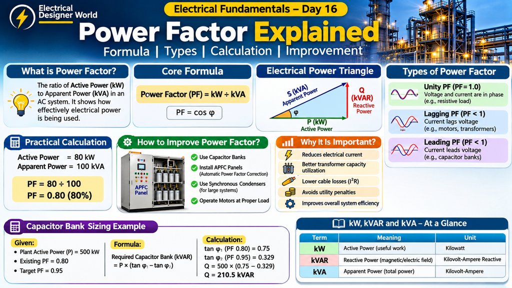
Power Factor (PF) is the ratio of Active Power (kW) to Apparent Power (kVA) in an AC electrical system.
In simple words, power factor tells us how effectively electrical power is being used to perform useful work.
Power Factor Formula:
Power Factor = Active Power ÷ Apparent Power
PF = kW ÷ kVA
For example, consider an electrical motor with:
- Active Power = 80 kW
- Apparent Power = 100 kVA
Calculation:
Power Factor = 80 ÷ 100
Power Factor = 0.80
Answer: Power Factor = 0.80 or 80%.
A higher power factor generally means that the electrical system uses its apparent power capacity more effectively.
To understand the relationship between electrical power and energy, read our guide on Electrical Power and Energy: Formulas and Examples.
2. Understanding the Three Types of Electrical Power
Before understanding power factor in detail, we need to understand three important types of power used in AC electrical systems.
A. Active Power (kW)
Active Power is also called Real Power or True Power.
It is the power that performs useful work in electrical equipment.
Examples:
- Rotating an electric motor.
- Producing heat in an electric heater.
- Producing light in a lamp.
- Operating electrical machinery.
Unit: Kilowatt (kW).
B. Reactive Power (kVAR)
Reactive Power is the power associated with establishing magnetic and electric fields in AC electrical equipment.
It is required by equipment such as motors and transformers to establish their magnetic fields.
Examples:
- Induction motors.
- Transformers.
- Reactors.
- Inductive electrical equipment.
Unit: Kilovolt-Ampere Reactive (kVAR).
C. Apparent Power (kVA)
Apparent Power is the combined effect of active power and reactive power in a sinusoidal AC system.
It represents the product of RMS voltage and RMS current.
Unit: Kilovolt-Ampere (kVA).
For a single-phase AC system:
Apparent Power (kVA) = Voltage × Current ÷ 1000
For a balanced three-phase AC system:
Apparent Power (kVA) = 1.732 × Line Voltage × Line Current ÷ 1000
Where:
- Line Voltage = Voltage between two phases.
- Line Current = Current flowing through the line.
- 1.732 = Square root of 3.
3. Understanding the Electrical Power Triangle
The relationship between active power, reactive power and apparent power can be explained using a Power Triangle.
The three sides represent:
- Horizontal side: Active Power (kW).
- Vertical side: Reactive Power (kVAR).
- Hypotenuse: Apparent Power (kVA).
Power Triangle Formula:
Apparent Power² = Active Power² + Reactive Power²
S² = P² + Q²
Where:
- S = Apparent Power.
- P = Active Power.
- Q = Reactive Power.
Power factor is calculated as:
Power Factor = Active Power ÷ Apparent Power
For sinusoidal AC systems:
Power Factor = cos φ
Here, φ (phi) is the phase angle between voltage and current.
Understanding this relationship is important when performing electrical load calculations and selecting electrical equipment.
4. What Are the Different Types of Power Factor?
There are three commonly discussed power factor conditions.
A. Unity Power Factor
Unity power factor means the power factor is equal to 1.
Power Factor = 1.0
In this condition, voltage and current are in phase for a sinusoidal system.
Example: A purely resistive load such as an ideal electric heating element.
B. Lagging Power Factor
A lagging power factor occurs when current lags behind voltage.
This commonly happens with inductive loads.
Examples:
- Induction motors.
- Transformers.
- Inductive reactors.
- Welding equipment.
Most industrial electrical systems have inductive loads, so lagging power factor is commonly encountered.
C. Leading Power Factor
A leading power factor occurs when current leads voltage.
This commonly happens when capacitive loads dominate the electrical system.
Examples:
- Capacitor banks.
- Overcompensated power factor correction systems.
5. Why Does Low Power Factor Occur?
Low power factor is a common problem in industrial electrical systems.
The main reason is the presence of inductive loads that require reactive power.
Some common causes are:
- Induction Motors: Motors require reactive power to establish their magnetic fields. Lightly loaded motors can have particularly poor power factors.
- Transformers: Transformers require magnetizing current to establish magnetic flux.
- Welding Machines: Certain welding machines draw significant reactive power.
- Inductive Equipment: Reactors and other inductive equipment consume reactive power.
- Lightly Loaded Equipment: Operating motors and transformers at very low loads can reduce their power factor.
Understanding these causes helps electrical engineers identify opportunities for power factor improvement.
6. Why Is Power Factor Important?
Power factor plays an important role in electrical system design and operation.
A. Reduces Electrical Current
For the same active power, voltage and system conditions, improving power factor reduces the current required.
Lower current can reduce electrical losses in cables and other equipment.
B. Improves Transformer Capacity Utilization
Transformers are generally rated in kVA.
A low power factor means more kVA capacity is required to deliver the same kW load.
Improving power factor can release some available transformer capacity.
C. Reduces Cable Losses
Electrical losses in cables are proportional to the square of current.
Formula:
Power Loss = Current² × Resistance
P(loss) = I² × R
When current decreases, cable losses also decrease, assuming resistance remains constant.
D. Helps Avoid Electricity Penalties
Some electricity utilities impose additional charges for poor power factor or reactive power consumption.
Improving power factor can help industrial facilities reduce such charges, depending on the applicable tariff.
E. Improves Electrical System Efficiency
A properly designed power factor correction system can improve the overall utilization of electrical equipment and reduce unnecessary current flow.
7. How to Calculate Power Factor – Practical Example
Let’s understand power factor calculation using a simple example.
Consider an industrial motor with the following electrical parameters:
- Active Power = 80 kW
- Apparent Power = 100 kVA
Calculate the power factor.
Step 1: Write the formula
Power Factor = Active Power ÷ Apparent Power
Step 2: Substitute the values
Power Factor = 80 ÷ 100
Step 3: Calculate
Power Factor = 0.80
Final Answer:
The motor has a power factor of 0.80 or 80%.
This means its apparent power requirement is 100 kVA to deliver 80 kW of active power.
8. How to Improve Power Factor?
Power factor can be improved using different electrical methods.
The most common industrial method is installing capacitor banks.
A. Capacitor Banks
Capacitors provide leading reactive power, which compensates for the lagging reactive power required by inductive loads.
This reduces the reactive power drawn from the electrical supply.
Capacitor banks are commonly installed in industrial electrical distribution systems.
For further technical understanding, refer to the Electrical Installation Guide – Power Factor Correction.
B. Automatic Power Factor Correction (APFC) Panels
An APFC panel automatically connects or disconnects capacitor steps depending on the electrical system’s power factor.
For example:
If the electrical system has a power factor of 0.75, the APFC controller can switch capacitor steps to improve it towards a preset target, such as 0.95.
C. Synchronous Condensers
An over-excited synchronous machine can supply reactive power and help improve power factor.
This method is generally used in larger electrical systems.
D. Proper Motor Loading
Avoid operating oversized motors continuously at very low loads when a correctly sized alternative is practical.
Proper motor selection and operation can help improve overall power factor.
9. Practical Capacitor Bank Sizing Calculation
Let’s understand how to calculate the required capacitor bank capacity for an industrial plant.
Given Data:
- Plant Active Power = 500 kW
- Existing Power Factor = 0.80
- Target Power Factor = 0.95
We need to calculate the required capacitor bank rating in kVAR.
Step 1: Write the formula
Required Capacitor Bank (kVAR) = P × (tan φ1 − tan φ2)
Where:
- P = Active power in kW.
- φ1 = Existing power factor angle.
- φ2 = Target power factor angle.
Step 2: Calculate the tangent values
Existing power factor = 0.80
tan φ1 = tan (cos⁻¹ 0.80)
tan φ1 = 0.75
Target power factor = 0.95
tan φ2 = tan (cos⁻¹ 0.95)
tan φ2 ≈ 0.329
Step 3: Substitute the values
Required Capacitor Bank = 500 × (0.75 − 0.329)
Required Capacitor Bank = 500 × 0.421
Required Capacitor Bank = 210.5 kVAR
Final Answer:
Required capacitor bank capacity ≈ 210.5 kVAR.
A suitable standard capacitor bank rating would be selected based on actual load variation, available ratings, harmonic conditions and engineering design requirements.
Important: This is a theoretical sizing calculation. Final capacitor bank selection must consider system voltage, switching arrangements, harmonic distortion, resonance and manufacturer’s specifications.
10. Practical EPC Electrical Design Applications
Power factor is important in EPC electrical engineering projects because it affects several stages of electrical system design.
A. Transformer Sizing
Transformers are rated in kVA.
For the same active power requirement, a lower power factor increases the required transformer kVA rating.
B. Generator Sizing
Generators have active power and apparent power ratings.
The power factor of connected loads must be considered when selecting a generator.
C. Cable Sizing
For a given active power and voltage, lower power factor results in higher current.
Higher current can influence cable sizing and voltage drop calculations.
D. Switchgear Selection
Electrical switchgear must be selected considering the system voltage, current, fault level and other design requirements.
Power factor influences normal operating current for a given kW load.
E. Capacitor Bank Selection
Electrical engineers calculate the required kVAR compensation and select suitable capacitor bank arrangements.
These calculations are important for industrial electrical distribution systems.
11. Difference Between kW, kVA and kVAR
| Parameter | Meaning | Unit |
|---|---|---|
| kW | Active Power | Kilowatt |
| kVA | Apparent Power | Kilovolt-Ampere |
| kVAR | Reactive Power | Kilovolt-Ampere Reactive |
Remember:
- kW represents active power.
- kVA represents apparent power.
- kVAR represents reactive power.
Understanding these three terms makes power factor calculations much easier.
12. Frequently Asked Questions (FAQs)
1. What is a good power factor?
A power factor close to 1.0 is generally desirable. Many industrial facilities target around 0.95 or higher, depending on utility requirements and operating conditions.
2. What happens when power factor is low?
Low power factor increases current for the same active power and voltage. This can increase electrical losses and reduce the available capacity of electrical equipment.
3. What is the difference between leading and lagging power factor?
In a lagging power factor, current lags behind voltage, commonly due to inductive loads.
In a leading power factor, current leads voltage, commonly due to capacitive loads.
4. Why are capacitor banks used in industries?
Capacitor banks provide reactive power compensation. They help reduce the reactive power drawn from the electrical supply and improve power factor.
5. Can power factor be equal to 1?
Yes. A unity power factor is equal to 1.0. It means active power and apparent power are equal for a sinusoidal system.
6. Does improving power factor reduce electricity consumption?
Power factor correction does not directly reduce the useful active energy required by a load. However, it can reduce current and associated distribution losses. It may also reduce electricity charges where low power factor penalties apply.
7. What is the formula for capacitor bank sizing?
Required Capacitor Bank (kVAR) = P × (tan φ1 − tan φ2)
Where P is active power in kW, and φ1 and φ2 are the existing and target power factor angles.
Conclusion
Power factor is an important concept in AC electrical engineering.
It helps electrical engineers understand the relationship between active power, reactive power and apparent power.
A good understanding of power factor i