
Three-Phase Power Calculations Explained: Formulas, Star and Delta Connections, kW, kVA and kVAR
Day 23 – Electrical Fundamentals: 30-Day Learning Course
Table of Contents
Simple Explanation
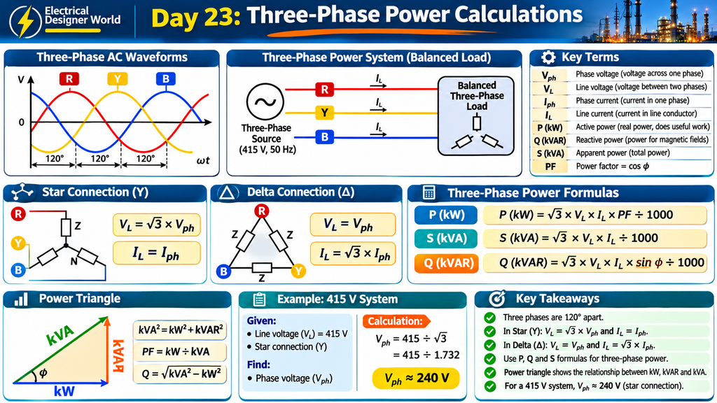
Three-phase electricity is widely used in industries because it can deliver large amounts of electrical power efficiently. It is commonly used to operate motors, pumps, compressors, transformers and other industrial equipment.
To understand three-phase power calculations, you need to know three important terms:
- kW: Actual power used by equipment to perform useful work.
- kVAR: Reactive power required to establish magnetic and electric fields.
- kVA: Total apparent power supplied to the equipment.
In this lesson, we will learn how to calculate voltage, current, power and power factor in three-phase electrical systems using simple formulas and practical examples.
Introduction
Three-phase electrical systems are the foundation of industrial power distribution.
Power stations, transformers, switchgear, motor control centres and industrial equipment commonly use three-phase electrical supplies.
Unlike a single-phase system, a three-phase system uses three alternating voltages that are separated from one another by 120 electrical degrees.
This arrangement provides a more continuous transfer of power and is particularly suitable for industrial motors and large electrical loads.
For electrical engineers, understanding three-phase power calculations is essential when calculating load current, selecting cables, checking transformer capacity, selecting circuit breakers and preparing electrical load lists.
In this lesson, we will cover:
- What a three-phase electrical system is.
- Phase voltage and line voltage.
- Phase current and line current.
- Star and delta connections.
- Active, reactive and apparent power.
- Three-phase power formulas.
- Power factor calculations.
- Practical numerical examples.
- Balanced and unbalanced loads.
- Applications in industrial electrical design.
1. What Is a Three-Phase Electrical System?
A three-phase electrical system consists of three alternating voltages with the same frequency and, in a balanced system, equal magnitude.
The three voltages are separated by 120 electrical degrees.
The phases are commonly identified as:
- R – Red phase.
- Y – Yellow phase.
- B – Blue phase.
In modern installations, the phase identification colours may differ depending on the applicable national standard and project specification. R, Y and B are commonly used as phase labels.
Why Is Three-Phase Power Used?
Three-phase power is widely used because:
- It can transmit large amounts of electrical power efficiently.
- It provides a rotating magnetic field for three-phase motors.
- It supports relatively smooth power transfer.
- It is suitable for industrial and commercial loads.
- It can supply both three-phase and single-phase loads in suitable four-wire systems.
Example: An industrial plant may use a three-phase supply to operate large motors and transformers, while single-phase loads such as lighting and socket outlets may be supplied from phase-to-neutral connections.
2. What Are Phase Voltage and Line Voltage?
Understanding the difference between phase voltage and line voltage is important for three-phase calculations.
Phase Voltage
Phase voltage is the voltage across one phase winding or between one phase and neutral in a star-connected system.
It is commonly represented by:
Vph = Phase voltage
Line Voltage
Line voltage is the voltage measured between any two phase conductors.
It is commonly represented by:
VL = Line voltage
For a balanced star-connected system:
VL = √3 × Vph
Therefore:
Vph = VL ÷ √3
Practical Example
Suppose a three-phase star-connected system has a line voltage of 415 V.
Phase voltage:
Vph = 415 ÷ 1.732
Vph ≈ 239.6 V
Therefore, the phase-to-neutral voltage is approximately 240 V.
This is why a typical 415 V three-phase, four-wire system provides approximately 240 V between phase and neutral.
3. What Are Phase Current and Line Current?
Phase Current
Phase current is the current flowing through an individual phase winding or load.
It is represented by:
Iph = Phase current
Line Current
Line current is the current flowing through a line conductor supplying the three-phase load.
It is represented by:
IL = Line current
The relationship between line current and phase current depends on whether the load is connected in star or delta.
4. What Is a Star Connection?
A star connection is also called a Y connection.
In this arrangement, one end of each of the three phase windings is connected together at a common point called the neutral point.
The other ends are connected to the three supply lines.
Star Connection Relationships
For a balanced star-connected load:
Line Voltage = √3 × Phase Voltage
VL = 1.732 × Vph
Line Current = Phase Current
IL = Iph
Example
Suppose:
- Line voltage = 415 V.
- Phase impedance = 20 Ω.
First, calculate phase voltage:
Vph = 415 ÷ 1.732
Vph ≈ 239.6 V
Now calculate phase current:
Iph = Vph ÷ Z
Iph = 239.6 ÷ 20
Iph ≈ 11.98 A
Since it is a star connection:
IL = Iph
Line current ≈ 11.98 A.
5. What Is a Delta Connection?
A delta connection is also called a Δ connection.
In this arrangement, the three phase windings are connected end-to-end to form a closed triangular circuit.
Each junction is connected to one of the three supply lines.
Delta Connection Relationships
For a balanced delta-connected load:
Line Voltage = Phase Voltage
VL = Vph
Line Current = √3 × Phase Current
IL = 1.732 × Iph
Example
Suppose:
- Line voltage = 415 V.
- Phase impedance = 20 Ω.
In a delta connection:
Vph = VL
Vph = 415 V
Now calculate phase current:
Iph = Vph ÷ Z
Iph = 415 ÷ 20
Iph = 20.75 A
Now calculate line current:
IL = 1.732 × Iph
IL = 1.732 × 20.75
Line current ≈ 35.94 A.
6. Difference Between Star and Delta Connections
| Parameter | Star Connection | Delta Connection |
|---|---|---|
| Connection shape | Y | Triangle |
| Neutral point | Available | Not normally available |
| Line voltage | √3 × phase voltage | Equal to phase voltage |
| Line current | Equal to phase current | √3 × phase current |
| Phase voltage | Line voltage ÷ √3 | Equal to line voltage |
| Common application | Distribution and motor starting arrangements | Motor running connections and three-phase loads |
The actual connection used depends on equipment design, supply voltage, load requirements and manufacturer instructions.
7. What Are kW, kVA and kVAR?
Three important quantities are used when calculating AC electrical power.
A. Active Power (kW)
Active power is the actual power converted into useful work, heat or light.
It is measured in kilowatts (kW).
Examples:
- Mechanical output from a motor.
- Heat produced by an electric heater.
- Light produced by lighting equipment.
B. Reactive Power (kVAR)
Reactive power is associated with energy stored and returned by inductive and capacitive elements during AC operation.
It is measured in kilovolt-amperes reactive (kVAR).
Examples:
- Magnetic fields in motors.
- Magnetic fields in transformers.
- Electric fields in capacitors.
C. Apparent Power (kVA)
Apparent power is the product of RMS voltage and RMS current, expressed in volt-amperes.
It is measured in kilovolt-amperes (kVA).
It represents the combined effect of active and reactive power for a sinusoidal system.
8. What Is Power Factor?
Power factor indicates how effectively apparent power is converted into active power in an AC electrical system.
For a sinusoidal system:
Power Factor = kW ÷ kVA
It is also expressed as:
PF = cos φ
Where φ is the phase angle between voltage and current.
Example
Suppose:
- Active power = 80 kW.
- Apparent power = 100 kVA.
Power factor = 80 ÷ 100
Power factor = 0.80
Therefore, the power factor is 0.80 or 80%.
A low power factor generally means more current is required to deliver the same active power at a given voltage.
9. Three-Phase Power Formulas
These formulas apply to balanced three-phase systems using RMS line values.
1. Apparent Power
S (kVA) = √3 × VL × IL ÷ 1000
Where:
- S = Apparent power in kVA.
- VL = Line voltage in volts.
- IL = Line current in amperes.
2. Active Power
P (kW) = √3 × VL × IL × PF ÷ 1000
Where:
- P = Active power in kW.
- VL = Line voltage in volts.
- IL = Line current in amperes.
- PF = Power factor.
3. Reactive Power
Q (kVAR) = √3 × VL × IL × sin φ ÷ 1000
Where:
- Q = Reactive power in kVAR.
- φ = Phase angle between voltage and current.
4. Power Factor
PF = kW ÷ kVA
5. Line Current from Active Power
IL = kW × 1000 ÷ (√3 × VL × PF)
These formulas are particularly useful when calculating industrial load currents and electrical equipment requirements.
10. Understanding the Three-Phase Power Triangle
The power triangle represents the relationship between active power, reactive power and apparent power.
It forms a right-angled triangle.
- Horizontal side: Active power (kW).
- Vertical side: Reactive power (kVAR).
- Hypotenuse: Apparent power (kVA).
Power Triangle Formula
kVA² = kW² + kVAR²
Therefore:
kVA = √(kW² + kVAR²)
And:
kVAR = √(kVA² − kW²)
Example
Suppose:
- Active power = 80 kW.
- Reactive power = 60 kVAR.
Apparent power:
kVA = √(80² + 60²)
kVA = √(6400 + 3600)
kVA = √10000
kVA = 100 kVA.
Power factor:
PF = 80 ÷ 100
PF = 0.80.
11. Practical Example 1 – Calculate Three-Phase Current
Suppose an industrial load has:
- Active power = 100 kW.
- Line voltage = 415 V.
- Power factor = 0.85.
Calculate the line current.
Step 1: Use the Current Formula
IL = kW × 1000 ÷ (1.732 × VL × PF)
Step 2: Substitute the Values
IL = 100 × 1000 ÷ (1.732 × 415 × 0.85)
IL = 100000 ÷ 610.95
IL ≈ 163.7 A.
Therefore, the approximate line current is 163.7 A.
This calculation is useful when estimating the current required by an industrial load.
12. Practical Example 2 – Calculate Apparent Power
Suppose a three-phase system has:
- Line voltage = 415 V.
- Line current = 50 A.
Calculate apparent power.
Formula:
S = √3 × VL × IL ÷ 1000
S = 1.732 × 415 × 50 ÷ 1000
S = 35.94 kVA
Apparent power ≈ 35.94 kVA.
13. Practical Example 3 – Calculate Active Power
Suppose:
- Line voltage = 415 V.
- Line current = 50 A.
- Power factor = 0.90.
Calculate active power.
Formula:
P = √3 × VL × IL × PF ÷ 1000
P = 1.732 × 415 × 50 × 0.90 ÷ 1000
Active power ≈ 32.35 kW.
14. Practical Example 4 – Calculate Reactive Power
Suppose:
- Apparent power = 100 kVA.
- Active power = 80 kW.
Calculate reactive power.
Formula:
Q = √(kVA² − kW²)
Q = √(100² − 80²)
Q = √(10000 − 6400)
Q = √3600
Reactive power = 60 kVAR.
15. Practical Example 5 – Calculate Three-Phase Motor Current
Consider a three-phase motor with:
- Rated output power = 30 kW.
- Supply voltage = 415 V.
- Efficiency = 90%.
- Power factor = 0.85.
Calculate the approximate full-load current.
Step 1: Calculate Electrical Input Power
Input Power = Output Power ÷ Efficiency
Input Power = 30 ÷ 0.90
Input Power = 33.33 kW
Step 2: Calculate Current
IL = Input Power × 1000 ÷ (1.732 × VL × PF)
IL = 33.33 × 1000 ÷ (1.732 × 415 × 0.85)
IL ≈ 54.6 A.
Therefore, the estimated full-load current is approximately 54.6 A.
Always use the manufacturer’s motor nameplate current for final cable and protection selection.
16. What Is a Balanced Three-Phase Load?
A balanced three-phase load has equal phase impedances and is supplied by balanced three-phase voltages.
In a balanced system:
- Phase voltages have equal magnitudes.
- Phase currents have equal magnitudes.
- Phase angles are separated by 120 degrees.
- The neutral current is zero in an ideal balanced star-connected four-wire system.
Balanced three-phase formulas are widely used in industrial electrical calculations.
17. What Is an Unbalanced Three-Phase Load?
An unbalanced load occurs when the electrical loads connected to the three phases are not equal.
For example:
- R phase load = 10 kW.
- Y phase load = 8 kW.
- B phase load = 6 kW.
The phase currents may become unequal.
In a four-wire star system, an unbalanced load can cause current to flow through the neutral conductor.
Common Causes
- Unequal single-phase loads.
- Incorrect load distribution.
- Uneven equipment operation.
- Faulty electrical connections.
- Different phase loading.
Why Is Load Balancing Important?
Load balancing helps:
- Reduce neutral current where applicable.
- Reduce phase-current imbalance.
- Improve equipment operating conditions.
- Reduce additional heating.
- Improve distribution-system performance.
18. What Is the Difference Between Single-Phase and Three-Phase Power?
| Parameter | Single-Phase | Three-Phase |
|---|---|---|
| Number of AC phases | One | Three |
| Voltage waveform | One alternating voltage | Three alternating voltages |
| Phase displacement | Not applicable between phases | 120 degrees |
| Common applications | Domestic and small commercial loads | Industrial and large commercial loads |
| Motor applications | Single-phase motors | Three-phase motors |
| Power transfer | Pulsating for a resistive load | Constant total instantaneous power for an ideal balanced load |
Both systems are important in electrical distribution. The choice depends on load requirements and the available supply.
19. Why Are Three-Phase Calculations Important in EPC Projects?
Three-phase power calculations are used throughout industrial electrical engineering.
1. Transformer Sizing
Engineers calculate the total apparent power demand in kVA to select a suitable transformer rating.
2. Cable Sizing
Load current is used as an input for cable current-capacity, voltage-drop and short-circuit checks.
3. Circuit Breaker Selection
Calculated load current helps determine suitable breaker ratings and protection settings.
4. Motor Feeder Design
Motor power, efficiency and power factor are used to estimate current and evaluate feeder requirements.
5. Electrical Load Lists
Electrical engineers prepare connected load, demand load, kW and kVA summaries for distribution-system design.
6. Generator Sizing
The total electrical demand and load characteristics help determine generator capacity.
7. Power Factor Correction
Reactive power calculations help estimate the capacitor-bank rating required for power factor improvement.
20. Common Mistakes in Three-Phase Power Calculations
Avoid these common errors:
- Using phase voltage instead of line voltage in a line-value power formula.
- Forgetting the √3 factor in balanced three-phase calculations.
- Confusing kW with kVA.
- Ignoring power factor when calculating current from active power.
- Ignoring motor efficiency when calculating motor input current from rated mechanical output power.
- Applying star relationships to a delta-connected load.
- Using balanced-load formulas without checking whether the load is balanced.
- Using calculated current alone to select cables or circuit breakers without checking installation and protection requirements.
Correctly identifying the connection and the type of power value is essential for accurate calculations.
21. Frequently Asked Questions
1. What is the three-phase power formula?
For a balanced three-phase system:
P (kW) = √3 × VL × IL × PF ÷ 1000.
2. Why is √3 used in three-phase power calculations?
The factor √3, approximately 1.732, comes from the relationship between line and phase quantities in a balanced three-phase system.
3. What is the difference between kW and kVA?
kW represents active power, while kVA represents apparent power.
4. What is kVAR?
kVAR represents reactive power associated with energy stored and returned by inductive and capacitive elements.
5. What is the power factor formula?
Power Factor = kW ÷ kVA for a sinusoidal system.
6. What is the relationship between line voltage and phase voltage in star?
Line Voltage = √3 × Phase Voltage.
7. What is the relationship between line current and phase current in delta?
Line Current = √3 × Phase Current.
8. Why is three-phase power preferred in industries?
It is suitable for large loads, provides a rotating magnetic field for three-phase motors and supports efficient industrial power distribution.
9. What is a balanced three-phase load?
A balanced load has equal phase impedances and equal phase currents in magnitude under balanced supply conditions.
10. How do you calculate three-phase motor current?
For a motor with rated mechanical output power:
Current = Output Power × 1000 ÷ (√3 × Voltage × Power Factor × Efficiency).
Use consistent units and the manufacturer’s nameplate data for final design.
22. Practice Questions
Test your understanding of three-phase power calculations.
Question 1: What is the phase displacement between three phases in a balanced system?
A. 60 degrees
B. 90 degrees
C. 120 degrees
D. 180 degrees
Question 2: What is the relationship between line voltage and phase voltage in a star connection?
A. VL = Vph
B. VL = √3 × Vph
C. VL = 3 × Vph
D. VL = Vph ÷ 3
Question 3: What is the relationship between line current and phase current in a delta connection?
A. IL = Iph
B. IL = Iph ÷ √3
C. IL = √3 × Iph
D. IL = 3 × Iph
Question 4: Which quantity represents active power?
A. kVAR
B. kVA
C. kW
D. Ohm
Question 5: What is the three-phase active power formula?
A. P = V × I
B. P = √3 × VL × IL × PF
C. P = I² × R only
D. P = V ÷ I
Question 6: A load has 80 kW active power and 100 kVA apparent power. What is its power factor?
A. 0.60
B. 0.70
C. 0.80
D. 0.90
Question 7: What is the unit of reactive power?
A. kW
B. kVA
C. kVAR
D. Volt
Question 8: What is the ideal neutral current of a balanced star-connected four-wire load?
A. Equal to phase current
B. Zero
C. Twice phase current
D. Three times phase current
Answers
- C – 120 degrees.
- B – VL = √3 × Vph.
- C – IL = √3 × Iph.
- C – kW.
- B – P = √3 × VL × IL × PF.
- C – 0.80.
- C – kVAR.
- B – Zero.
Conclusion
Three-phase power calculations are essential for understanding industrial electrical systems.
By learning line voltage, phase voltage, line current, phase current, star and delta connections, active power, reactive power, apparent power and power factor, you can understand how electrical loads operate and how electrical power is calculated.
For EPC electrical engineers, these calculations are particularly important when preparing load lists, sizing transformers, selecting cables and circuit breakers, estimating motor current and designing industrial power distribution systems.
Continue learning with Electrical Designer World and strengthen your electrical engineering fundamentals step by step.
Continue the 30-Day Electrical Fundamentals Course
This lesson is part of the Electrical Fundamentals – 30-Day Learning Course.
- Previous lesson: Day 22 – Electrical Switchgear and Protection Devices.
- Current lesson: Day 23 – Three-Phase Power Calculations.
- Next lesson: Day 24 – Network Theorems.
Explore more electrical engineering lessons at Electrical Designer World.
1. All About Circuits – Three-Phase AC Systems
For a deeper understanding of three-phase AC systems, phase relationships, star connections and delta connections, explore the All About Circuits Electrical Engineering Textbook.
2. Electrical Engineering – Three-Phase Power
For additional learning about three-phase power, electrical quantities and AC circuit calculations, refer to the Electrical Engineering Portal.
3. NPTEL – Electrical Engineering Courses
To strengthen your understanding of electrical engineering fundamentals and power systems, explore the NPTEL online learning platform.
2 thoughts on “Three-Phase Power Calculations: Formulas, Star, Delta & Examples”