
Earthing and Electrical Safety – Types, Working, Importance and Protection
Table of Contents
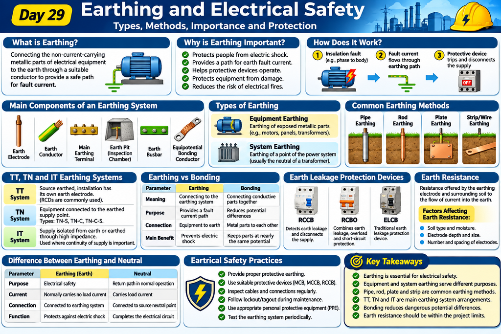
Introduction
Earthing is one of the most important safety features in an electrical installation. It protects people from electric shock and helps prevent damage to electrical equipment.
In simple words, earthing means connecting the non-current-carrying metallic parts of electrical equipment to the ground through a suitable conductor.
For example, if a motor develops an insulation fault, its metallic body may become live. If proper earthing is provided, fault current can flow through the earthing path, allowing the protective device to disconnect the supply.
Earthing is widely used in residential buildings, industries, power plants, substations and EPC projects.
In this lesson, we will understand how earthing works, its different types, components and importance in electrical safety.
1. What Is Earthing?
Earthing is the process of connecting the metallic body of electrical equipment to the earth through an appropriate earthing conductor and electrode.
The main purpose is to provide a safe path for fault current and reduce the risk of electric shock.
Example:
Consider an electric motor connected to a three-phase power supply.
If the insulation inside the motor fails, the motor body may become electrically live.
When proper earthing is provided, fault current flows through the protective earthing path. The protective device detects the fault and disconnects the electrical supply.
This helps protect people and equipment.
2. Why Is Earthing Important?
Earthing plays an important role in electrical safety.
Its main purposes include:
- Protecting people from electric shock.
- Providing a path for earth fault current.
- Helping protective devices operate during faults.
- Protecting electrical equipment from damage.
- Reducing the risk of electrical fires.
- Providing a reference point for system voltage.
- Improving the safety and reliability of electrical installations.
Without proper earthing, exposed metallic parts of electrical equipment can become dangerous during insulation failure.
3. How Does an Earthing System Work?
An earthing system provides a conductive path for fault current to return to its source.
Let’s understand with a simple example.
Imagine a motor connected to a three-phase electrical supply.
During normal operation, current flows through the phase conductors to operate the motor.
Now imagine that the insulation inside the motor fails and a phase conductor touches the motor body.
The motor body can become live.
With proper protective earthing:
- Fault current flows through the protective earth conductor.
- The fault current creates an abnormal electrical condition.
- The protective device detects the fault.
- The circuit breaker or other protective device disconnects the supply.
This reduces the risk of electric shock and equipment damage.
4. Main Components of an Earthing System
An earthing system consists of several important components.
1. Earth Electrode
An earth electrode is a conductive metal component installed in the ground to establish an electrical connection with the earth.
Examples include copper-bonded rods, copper electrodes and galvanized steel electrodes.
2. Earth Conductor
An earth conductor connects the electrical installation or equipment to the earthing system.
3. Main Earthing Terminal
It is the main connection point where protective conductors and earthing connections are brought together.
4. Earth Pit or Inspection Chamber
An earth pit provides access to the earth electrode connection for inspection and testing.
5. Earth Busbar
An earth busbar provides a common connection point for multiple protective earthing conductors.
6. Equipotential Bonding Conductor
Bonding conductors connect metallic parts together to reduce dangerous potential differences.
5. Types of Earthing
Earthing systems are commonly classified based on their application and arrangement.
A. Equipment Earthing
Equipment earthing means connecting the exposed metallic body of electrical equipment to the protective earthing system.
Examples include:
- Motor bodies.
- Transformer tanks.
- Electrical panels.
- Cable trays.
- Switchgear enclosures.
- Generator frames.
The main purpose is to protect people from electric shock during insulation failure.
B. System Earthing
System earthing means connecting a point of the electrical power system, usually the neutral point, to earth.
For example, the neutral point of a transformer may be earthed to establish a reference voltage and provide a defined path for earth fault current.
System earthing helps improve the stability and safety of electrical power systems.
6. Common Earthing Methods
Different earthing arrangements are used depending on soil conditions, installation requirements and applicable electrical standards.
1. Pipe Earthing
A metal pipe is installed vertically in the ground to provide an electrical connection with the earth.
It is commonly used in building electrical installations.
2. Rod Earthing
A copper or copper-bonded steel rod is driven into the ground.
It is used in residential, commercial and industrial installations.
3. Plate Earthing
A metal plate, usually copper or galvanized steel, is buried in the ground to provide an earth connection.
4. Strip or Wire Earthing
A metal strip or conductor is buried in the ground to form an earthing connection.
It is commonly used in industrial installations and large electrical facilities.
7. What Are TT, TN and IT Earthing Systems?
In electrical installations, earthing arrangements are also classified into TT, TN and IT systems.
These systems describe how the power source and exposed metallic parts of electrical equipment are connected to earth.
A. TT System
In a TT system, the power supply source is earthed, and the installation has its own local earth electrode for equipment protection.
Residual current devices (RCDs) are commonly used for protection against earth leakage.
B. TN System
In a TN system, exposed metallic parts of electrical equipment are connected to the earthed point of the power supply through protective conductors.
TN systems are further classified into:
- TN-S: Neutral and protective earth conductors are separate throughout the system.
- TN-C: Neutral and protective earth functions are combined in one conductor.
- TN-C-S: Neutral and protective earth functions are combined in part of the system and separated in the installation.
C. IT System
In an IT system, the power supply is isolated from earth or connected to earth through a high impedance.
The exposed metallic parts of equipment are connected to earth.
This arrangement is used in specific installations where continuity of supply is important, such as certain medical and industrial applications.
8. Difference Between Earthing and Bonding
Earthing and bonding are related but different electrical safety concepts.
| Parameter | Earthing | Bonding |
|---|---|---|
| Meaning | Connecting to the earthing system | Connecting conductive parts together |
| Purpose | Provides a fault current path | Reduces potential differences |
| Connection | Equipment to protective earth | Metal parts to each other |
| Main benefit | Helps prevent electric shock | Reduces dangerous touch voltage |
Simple explanation:
Earthing connects electrical equipment to the protective earthing system.
Bonding connects metallic parts together to help keep them at nearly the same electrical potential.
Both are important for electrical safety.
9. What Is an Earth Leakage Circuit Breaker?
An earth leakage protection device detects leakage current and disconnects the electrical supply when the operating conditions exceed its specified limits.
Common devices include:
1. RCCB (Residual Current Circuit Breaker)
An RCCB detects an imbalance between the outgoing and returning currents and disconnects the circuit when residual current exceeds its rated operating value.
2. RCBO (Residual Current Breaker with Overcurrent Protection)
An RCBO combines residual current protection with overload and short-circuit protection.
3. ELCB (Earth Leakage Circuit Breaker)
ELCB is a traditional term commonly associated with voltage-operated earth leakage protection devices. Modern installations generally use current-operated RCDs such as RCCBs and RCBOs.
These devices provide additional protection against electric shock and earth leakage. They do not replace protective earthing.
10. Electrical Safety Practices
Following proper electrical safety practices helps prevent accidents and equipment damage.
Important safety practices include:
- Always provide proper protective earthing.
- Never touch exposed live electrical conductors.
- Use suitable protective equipment when working on electrical installations.
- Inspect cables and electrical connections regularly.
- Use correctly rated protective devices.
- Test earthing systems periodically.
- Follow lockout/tagout procedures before electrical maintenance.
- Avoid working on energized equipment unless specifically authorized and controlled procedures permit it.
- Maintain proper electrical clearance.
- Follow applicable electrical safety standards and regulations.
Important: Electrical work should only be performed by qualified and authorized personnel using appropriate safety procedures.
11. Importance of Earthing in EPC Projects
Earthing is an essential part of electrical engineering design in EPC projects.
Electrical engineers must consider earthing requirements during electrical system design, equipment selection, installation and commissioning.
Earthing is important for:
- Transformer body earthing.
- Generator body earthing.
- Motor body earthing.
- Switchgear and electrical panel earthing.
- Cable tray earthing and bonding.
- Structural steel bonding.
- Lightning protection systems.
- Substation earthing grids.
- Instrumentation and control system earthing.
Practical EPC Example
Consider an industrial plant containing:
- One transformer.
- Multiple electrical panels.
- Several motors.
- Cable trays.
- Structural steel platforms.
All exposed conductive parts must be connected to the appropriate protective earthing system.
The electrical engineering team prepares earthing layouts, earthing connection details, equipment earthing schedules and earthing calculations.
During commissioning, the earthing system is inspected and tested to verify that it meets the project specifications and applicable standards.
12. What Is Earth Resistance?
Earth resistance is the resistance offered by the earthing electrode and surrounding soil to the flow of electrical current into the earth.
Lower earth resistance is generally desirable, but the acceptable value depends on the installation, earthing arrangement and applicable standards.
Earth resistance is influenced by:
- Soil type.
- Soil moisture.
- Soil temperature.
- Electrode depth.
- Electrode size.
- Number of electrodes.
- Distance between electrodes.
An earth resistance tester is commonly used to measure the resistance of an earth electrode system.
The measured value must be compared with the applicable design requirements and electrical standards.
13. Difference Between Earthing and Neutral
Many beginners confuse earthing and neutral, but they have different functions.
| Parameter | Earthing | Neutral |
|---|---|---|
| Purpose | Electrical safety | Provides a return path in normal operation |
| Current | Normally carries no load current | Normally carries load current in applicable circuits |
| Connection | Connected to the protective earthing system | Connected to the source neutral point |
| Function | Helps protect against electric shock | Completes the electrical circuit |
Remember: Neutral and earth are not interchangeable. They must be connected only at designated points as required by the electrical system design and applicable standards.
14. Key Takeaways
- Earthing is essential for electrical safety.
- It helps protect people from electric shock.
- It provides a path for fault current.
- Equipment earthing and system earthing have different purposes.
- Pipe, rod, plate and strip earthing are common methods.
- TT, TN and IT are common earthing system arrangements.
- Bonding helps reduce dangerous potential differences.
- RCCBs and RCBOs provide additional protection against residual current.
- Earth resistance must be verified against project requirements.
- Proper earthing design is essential in EPC projects.
15. Frequently Asked Questions (FAQs)
1. What is the main purpose of earthing?
The main purpose of earthing is to protect people from electric shock by providing a suitable path for fault current and helping protective devices disconnect the supply.
2. What are the common types of earthing?
Common earthing methods include pipe earthing, rod earthing, plate earthing and strip earthing.
3. What is the difference between earthing and grounding?
The terms are often used interchangeably. In many engineering contexts, earthing is commonly used in IEC-based terminology, while grounding is widely used in North American terminology.
4. What is an earth electrode?
An earth electrode is a conductive metal component installed in the ground to establish an electrical connection with the earth.
5. What is an RCCB?
An RCCB is a protective device that detects residual current and disconnects the electrical supply when leakage exceeds its specified operating value.
6. What is earth resistance?
Earth resistance is the resistance offered by the earthing electrode and surrounding soil to electrical current flowing into the earth.
7. Can neutral and earth be connected together?
Neutral and earth must only be connected at designated points according to the earthing system design and applicable electrical standards. They should not be connected together randomly at distribution boards or equipment.
Related Articles
To build a strong foundation in electrical engineering, follow our Electrical Fundamentals – Zero to Advanced Course.
Before learning about earthing and electrical safety, understand different fault conditions in power systems through our guide on Electrical Faults – Types, Causes, Effects and Protection.
External References
For more information about electrical safety, earthing and protection practices, refer to these trusted resources:
- OSHA – Electrical Safety
- Electrical Safety Foundation International (ESFI)
- Central Electricity Authority (CEA), India
Conclusion
Earthing is one of the most important parts of electrical system design and safety.
It protects people, electrical equipment and installations by providing a suitable path for fault current and helping protective devices operate correctly.
Every electrical engineer should understand earthing methods, earthing arrangements, bonding, earth resistance and electrical safety practices.
Proper earthing design, installation, inspection and testing are essential for safe and reliable electrical installations.
In the next lesson, we will learn about Electrical Protection Systems and understand how protective relays, circuit breakers and other protection devices work together to protect electrical equipment.