
Day 24: Network Theorems – Superposition, Thevenin, Norton and Maximum Power Transfer
Electrical Fundamentals – 30-Day Learning Course
Table of Contents
Simple Summary
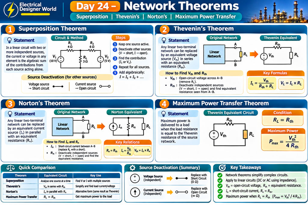
Network theorems are methods used to simplify electrical circuits and solve for voltage, current and power. Instead of solving a complicated circuit all at once, these theorems allow us to break it into smaller, easier problems.
In this lesson, you will learn four important network theorems:
- Superposition Theorem
- Thevenin’s Theorem
- Norton’s Theorem
- Maximum Power Transfer Theorem
1. Introduction to Network Theorems
An electrical circuit may contain several voltage sources, current sources, resistors and loads connected in different ways. Calculating the current and voltage in every component can become difficult, especially when the circuit has multiple sources.
Network theorems provide systematic methods to simplify these circuits.
They are widely used in electrical engineering for:
- Circuit analysis and troubleshooting.
- Understanding voltage and current distribution.
- Analysing electrical and electronic circuits.
- Studying power supplies and control circuits.
- Simplifying complex linear networks.
Before learning the theorems, understand one important term.
Linear circuit: A circuit in which the voltage and current have a proportional relationship and the circuit parameters remain constant. Ideal resistors are linear components.
The basic network theorems in this lesson apply to linear circuits. Their AC applications use impedance and phasors instead of resistance alone.
2. Superposition Theorem
What is the Superposition Theorem?
The Superposition Theorem states that:
In a linear circuit containing two or more independent sources, the current or voltage in any component is equal to the algebraic sum of the individual contributions produced by each independent source acting separately.
In simple words, consider a circuit with two voltage sources. Instead of analysing both sources together, analyse one source at a time and then combine the results.
Steps to Apply the Superposition Theorem
- Identify all independent voltage and current sources.
- Select one independent source and keep it active.
- Deactivate all other independent sources:
- Replace an ideal voltage source with a short circuit.
- Replace an ideal current source with an open circuit.
- Calculate the current or voltage caused by the active source.
- Repeat the process for each independent source.
- Add the individual contributions algebraically, considering their directions and polarities.
Important: Dependent sources must remain active. Also, calculate power from the final voltage or current; do not directly add the individual power contributions.
Practical Example – Superposition Theorem
Consider a simple series circuit with:
- Voltage source 1 = 10 V
- Voltage source 2 = 5 V
- Both sources oppose each other.
- Resistance = 5 Ω
Find the current through the resistor.
Step 1: Consider the 10 V source alone.
Deactivate the 5 V ideal voltage source by replacing it with a short circuit.
Current due to 10 V source:
I₁ = V ÷ R
I₁ = 10 ÷ 5
I₁ = 2 A
Step 2: Consider the 5 V source alone.
Deactivate the 10 V ideal voltage source by replacing it with a short circuit.
Because the 5 V source acts in the opposite direction:
I₂ = -5 ÷ 5
I₂ = -1 A
Step 3: Add the contributions.
Total current = I₁ + I₂
Total current = 2 + (-1)
Total current = 1 A
The negative sign indicates that the second source acts opposite to the chosen reference direction.
3. Thevenin’s Theorem
What is Thevenin’s Theorem?
Thevenin’s Theorem states that any linear two-terminal network containing voltage sources, current sources and resistances or impedances can be represented by an equivalent voltage source connected in series with an equivalent resistance or impedance.
In simple words, a complicated circuit can be replaced with:
- One equivalent voltage source (Vth).
- One equivalent series resistance (Rth).
- The load connected across the output terminals.
This simplified circuit is called the Thevenin equivalent circuit.
Important Terms
Thevenin voltage (Vth): The open-circuit voltage measured across the two load terminals after removing the load.
Thevenin resistance (Rth): The equivalent resistance measured looking into the two load terminals after deactivating all independent sources.
Steps to Apply Thevenin’s Theorem
- Identify the load resistor.
- Remove the load resistor from the circuit.
- Calculate the open-circuit voltage across the load terminals. This is Vth.
- Deactivate all independent sources:
- Ideal voltage source → short circuit.
- Ideal current source → open circuit.
- Calculate the equivalent resistance looking into the open load terminals. This is Rth.
- Draw the equivalent circuit using Vth in series with Rth.
- Reconnect the load and calculate the required current or voltage.
Practical Example – Thevenin’s Theorem
Consider a circuit containing:
- Supply voltage = 12 V
- R1 = 4 Ω
- R2 = 8 Ω
- Load resistance RL = 4 Ω
R1 is connected in series with the supply, and R2 is connected from the output node to ground. The load is connected across the same output terminals as R2.
Find the load current using Thevenin’s Theorem.
Step 1: Remove the load resistor.
Disconnect RL = 4 Ω from the output terminals.
Step 2: Calculate Thevenin voltage.
Using the voltage divider formula:
Vth = Vs × R2 ÷ (R1 + R2)
Vth = 12 × 8 ÷ (4 + 8)
Vth = 96 ÷ 12
Vth = 8 V
Step 3: Calculate Thevenin resistance.
Replace the ideal 12 V source with a short circuit.
Rth = R1 × R2 ÷ (R1 + R2)
Rth = 4 × 8 ÷ (4 + 8)
Rth = 32 ÷ 12
Rth = 2.67 Ω (approximately)
Step 4: Reconnect the load.
Load resistance RL = 4 Ω.
Load current:
IL = Vth ÷ (Rth + RL)
IL = 8 ÷ (2.67 + 4)
IL ≈ 1.2 A
Therefore, the load current is approximately 1.2 A.
Link to the complete course:
Continue learning with our Electrical Fundamentals – Zero to Advanced course, covering essential electrical concepts, circuit analysis, power systems and practical engineering topics.
Link to the website:
Explore more electrical engineering tutorials, design concepts and learning resources at Electrical Designer World.
4. Norton’s Theorem
What is Norton’s Theorem?
Norton’s Theorem states that any linear two-terminal electrical network can be represented by an equivalent current source connected in parallel with an equivalent resistance or impedance.
In simple words, a complicated circuit can be simplified into:
- One equivalent current source (In).
- One parallel resistance (Rn).
- The load connected across the output terminals.
Important Terms
Norton current (In): The short-circuit current flowing between the two output terminals after removing the load.
Norton resistance (Rn): The equivalent resistance looking into the output terminals after deactivating all independent sources.
For a linear two-terminal network:
Rn = Rth
In = Vth ÷ Rth
Steps to Apply Norton’s Theorem
- Remove the load resistor.
- Short-circuit the two output terminals.
- Calculate the short-circuit current. This is Norton current (In).
- Deactivate all independent sources and calculate the equivalent resistance looking into the terminals.
- Draw the equivalent circuit with In in parallel with Rn.
- Reconnect the load and calculate its current or voltage.
Practical Example – Norton’s Theorem
Use the same circuit from the Thevenin example:
- Supply voltage = 12 V
- R1 = 4 Ω
- R2 = 8 Ω
- Load resistance RL = 4 Ω
From the Thevenin calculation:
Vth = 8 V
Rth = 2.67 Ω
Step 1: Calculate Norton resistance.
Rn = Rth
Rn = 2.67 Ω
Step 2: Calculate Norton current.
In = Vth ÷ Rth
In = 8 ÷ 2.67
In ≈ 3 A
Step 3: Reconnect the load.
Using the current divider formula:
IL = In × Rn ÷ (Rn + RL)
IL = 3 × 2.67 ÷ (2.67 + 4)
IL ≈ 1.2 A
Therefore, the load current is approximately 1.2 A, the same result obtained using Thevenin’s Theorem.
5. Maximum Power Transfer Theorem
What is the Maximum Power Transfer Theorem?
The Maximum Power Transfer Theorem states that maximum power is delivered to a load when the load resistance is equal to the Thevenin resistance of the source network.
For a DC resistive circuit:
RL = Rth
In simple words, maximum power reaches the load when the load resistance matches the equivalent resistance of the source network.
Formula for Maximum Power Transfer
For a DC resistive circuit:
RL = Rth
Maximum load power:
Pmax = Vth² ÷ (4 × Rth)
Where:
- Pmax = Maximum power delivered to the load.
- Vth = Thevenin voltage.
- Rth = Thevenin resistance.
- RL = Load resistance.
Practical Example – Maximum Power Transfer
Consider:
- Thevenin voltage = 12 V
- Thevenin resistance = 4 Ω
Find the load resistance required for maximum power transfer.
According to the theorem:
RL = Rth
RL = 4 Ω
Now calculate maximum power:
Pmax = Vth² ÷ (4 × Rth)
Pmax = 12² ÷ (4 × 4)
Pmax = 144 ÷ 16
Pmax = 9 W
Therefore, maximum power is transferred when the load resistance is 4 Ω, and the maximum load power is 9 W.
Important: At the maximum power transfer condition in a simple DC resistive circuit, the load receives only 50% of the power supplied by the Thevenin equivalent source. This is why maximum power transfer is not necessarily the most efficient operating condition for power distribution systems.
For AC circuits, maximum average power transfer occurs when the load impedance is the complex conjugate of the source’s Thevenin impedance.
6. Comparison of Network Theorems
| Theorem | Main Principle | Equivalent Circuit |
|---|---|---|
| Superposition | Analyse one independent source at a time | Individual voltage/current contributions |
| Thevenin | Replace a network with a voltage source | Vth in series with Rth |
| Norton | Replace a network with a current source | In in parallel with Rn |
| Maximum Power Transfer | Match load resistance to source resistance | RL = Rth for DC resistive circuits |
7. Thevenin vs Norton – Important Relationship
Thevenin’s and Norton’s theorems are closely related.
Thevenin equivalent:
- Voltage source = Vth
- Series resistance = Rth
Norton equivalent:
- Current source = In
- Parallel resistance = Rn
Conversion formulas:
In = Vth ÷ Rth
Vth = In × Rn
Rn = Rth
Both equivalent circuits produce the same voltage and current at the load terminals.
8. Where Are Network Theorems Used?
Network theorems are useful in several electrical engineering applications.
Electrical circuit design: To simplify complex circuits and calculate branch currents and voltages.
Power supply circuits: To understand the behaviour of sources and loads.
Electronic circuits: To analyse linear portions of electronic networks.
Troubleshooting: To isolate a section of a circuit and determine its equivalent behaviour.
Communication circuits: Impedance matching is important in signal transfer and transmission systems.
Electrical engineering studies: These theorems are fundamental tools for analysing DC and AC circuits.
In practical EPC electrical design, network theorems are mainly learning and analysis tools. Actual power-system studies such as load flow, short-circuit analysis and protection coordination use more detailed methods and equipment models.
9. Common Mistakes to Avoid
- Replacing an ideal voltage source with an open circuit instead of a short circuit.
- Replacing an ideal current source with a short circuit instead of an open circuit.
- Forgetting to remove the load when calculating Thevenin voltage.
- Confusing Thevenin resistance with the load resistance.
- Ignoring current direction and polarity in superposition calculations.
- Adding individual power contributions directly in the superposition method.
- Assuming maximum power transfer always means maximum efficiency.
- Applying resistance-only formulas to AC circuits without considering impedance.
10. Frequently Asked Questions
Q1. What are network theorems?
Network theorems are techniques used to simplify electrical circuits and calculate voltage, current and power.
Q2. What are the four important network theorems?
The four theorems covered in this lesson are Superposition, Thevenin’s, Norton’s and Maximum Power Transfer.
Q3. What is the difference between Thevenin and Norton?
Thevenin represents a circuit using a voltage source in series with resistance. Norton represents it using a current source in parallel with resistance.
Q4. Can Superposition Theorem be used for power calculations?
Not directly. Superposition is used to calculate voltage and current. Calculate power using the final combined voltage or current.
Q5. What happens when load resistance equals Thevenin resistance?
For a DC resistive circuit, maximum power is transferred to the load when RL = Rth.
Q6. Are network theorems applicable to AC circuits?
Yes. They can be applied to linear AC circuits using impedance and phasor calculations.
Q7. Can network theorems be used in circuits with dependent sources?
Yes. Dependent sources must remain active when applying superposition. When calculating equivalent resistance in a network with dependent sources, use an appropriate test source method if necessary.
11. Practice Questions
Test your understanding of today’s lesson.
- What is the Superposition Theorem?
- What happens to an ideal voltage source when it is deactivated?
- What happens to an ideal current source when it is deactivated?
- What are Vth and Rth?
- What is Norton current?
- What is the relationship between Thevenin and Norton resistance?
- State the condition for maximum power transfer in a DC resistive circuit.
- A Thevenin equivalent circuit has Vth = 10 V and Rth = 5 Ω. Calculate the Norton current.
- If Rth = 6 Ω, what load resistance gives maximum power transfer?
- Why should power not be calculated by directly adding the individual power contributions in superposition?
Answers
- It states that the total voltage or current in a linear circuit is the algebraic sum of individual contributions from each independent source acting separately.
- Replace it with a short circuit.
- Replace it with an open circuit.
- Vth is open-circuit voltage; Rth is equivalent resistance looking into the load terminals with independent sources deactivated.
- The short-circuit current at the output terminals.
- Rn = Rth.
- RL = Rth.
- In = Vth ÷ Rth = 10 ÷ 5 = 2 A.
- RL = 6 Ω.
- Power is generally a nonlinear function of voltage and current. First combine the voltage or current contributions, then calculate power.
Conclusion
Network theorems make electrical circuit analysis easier and more systematic.
Remember these four key ideas:
- Superposition: Analyse one independent source at a time.
- Thevenin: Replace a network with an equivalent voltage source and series resistance.
- Norton: Replace a network with an equivalent current source and parallel resistance.
- Maximum Power Transfer: Match load resistance to Thevenin resistance for maximum power in a DC resistive circuit.
Understanding these theorems will strengthen your electrical fundamentals and help you analyse more complex circuits with confidence.
For additional learning and circuit analysis practice, explore these resources:
Continue Learning – Electrical Fundamentals
- Previous lesson: Day 23 – Three-Phase Power Calculations
- Current lesson: Day 24 – Network Theorems
- Next lesson: Day 25 – Series Resonance and Parallel Resonance
Explore the complete Electrical Fundamentals – Zero to Advanced course for the full learning sequence.