
Capacitors and Inductors Explained: Working Principle, Types, Formulas and Applications
Day 17 – Electrical Fundamentals: 30-Day Learning Course
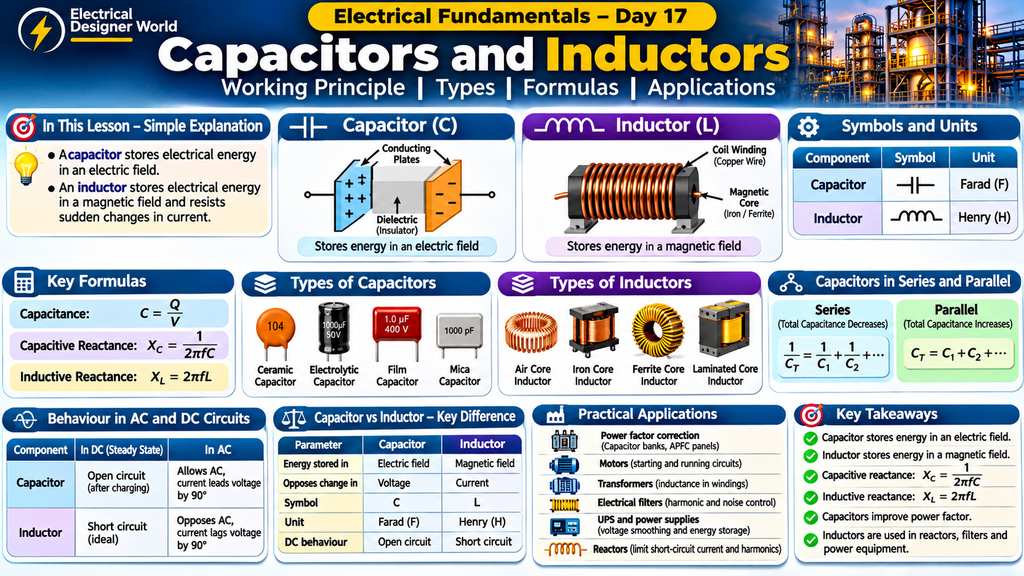
In This Lesson – Simple Explanation
Table of Contents
Think of a capacitor as a small electrical storage device that stores energy in an electric field. An inductor is a coil of wire that stores energy in a magnetic field and resists sudden changes in current.
Both components are essential in electrical systems. Capacitors help improve power factor, while inductors are used in transformers, motors, reactors and electrical filters.
In this lesson, we will understand how they work, their types, formulas and practical applications in simple language.
Introduction
Have you ever wondered how electrical equipment stores electrical energy, controls current flow or reduces unwanted electrical signals?
Two important electrical components help perform these functions: Capacitors and Inductors.
Capacitors and inductors are widely used in electrical and electronic systems. They are found in power supplies, motors, transformers, capacitor banks, electrical filters, UPS systems and many other applications.
Although both components can store energy, they work differently.
- A capacitor stores energy in an electric field.
- An inductor stores energy in a magnetic field.
Understanding these two components is important for electrical engineering students, electrical designers and EPC professionals.
1. What Is a Capacitor?
A capacitor is an electrical component that stores electrical energy in an electric field.
It consists of two conducting plates separated by an insulating material called a dielectric.
When a voltage is applied across the capacitor, electrical charges accumulate on its plates.
One plate becomes positively charged, while the other becomes negatively charged.
This separation of electrical charges creates an electric field between the plates, allowing the capacitor to store energy.
Construction of a Capacitor
A basic capacitor consists of three main parts:
- Positive conducting plate.
- Negative conducting plate.
- Dielectric material between the plates.
Common dielectric materials include:
- Ceramic.
- Paper.
- Plastic film.
- Mica.
- Aluminium oxide.
The dielectric prevents direct electrical contact between the conducting plates.
How Does a Capacitor Work?
Let’s understand the working principle step by step.
Step 1: Connecting the Supply
When a capacitor is connected to a DC power supply, current initially flows through the circuit.
Step 2: Charge Accumulation
Positive and negative charges accumulate on opposite plates of the capacitor.
Step 3: Electric Field Formation
An electric field develops between the plates.
Step 4: Fully Charged Condition
As the capacitor charges, its voltage increases.
When the capacitor voltage reaches the DC supply voltage, charging current stops flowing in an ideal circuit.
The capacitor is now fully charged.
Important: A charged capacitor can retain electrical energy even after the power supply is disconnected.
2. What Is Capacitance?
Capacitance is the ability of a capacitor to store electrical charge for a given voltage.
It is represented by the letter C.
The SI unit of capacitance is the Farad (F).
Capacitance Formula
Capacitance = Charge ÷ Voltage
C = Q ÷ V
Where:
- C = Capacitance in Farads (F).
- Q = Electrical charge in Coulombs (C).
- V = Voltage in Volts (V).
Practical Example
Consider a capacitor that stores:
- Electrical Charge = 0.02 C
- Voltage = 10 V
Calculate its capacitance.
Calculation:
Capacitance = 0.02 ÷ 10
Capacitance = 0.002 F
Answer: 0.002 Farad or 2,000 µF.
This means the capacitor has a capacitance of 2,000 microfarads.
3. Types of Capacitors
Different types of capacitors are used depending on their electrical ratings and applications.
A. Ceramic Capacitor
Ceramic capacitors use ceramic material as the dielectric.
Applications:
- Electronic circuits.
- Noise filtering.
- High-frequency circuits.
- Bypass applications.
B. Electrolytic Capacitor
Electrolytic capacitors provide relatively high capacitance values in compact sizes.
Applications:
- Power supply circuits.
- DC link circuits.
- UPS systems.
- Electronic equipment.
Many electrolytic capacitors are polarized, meaning their positive and negative terminals must be connected correctly.
C. Film Capacitor
Film capacitors use plastic film as the dielectric material.
Applications:
- Motor run circuits.
- Electrical filters.
- Power electronics.
- Power factor correction systems.
D. Mica Capacitor
Mica capacitors use mica as the dielectric material.
Applications:
- High-frequency circuits.
- Radio frequency equipment.
- Precision electronic circuits.
4. Capacitors in Series and Parallel
Capacitors can be connected in series or parallel depending on the required capacitance and voltage rating.
A. Capacitors in Series
When capacitors are connected in series, the total capacitance decreases.
Formula:
1 ÷ C(total) = 1 ÷ C1 + 1 ÷ C2 + 1 ÷ C3
For two capacitors:
C(total) = (C1 × C2) ÷ (C1 + C2)
Example:
Two capacitors are connected in series:
- C1 = 10 µF
- C2 = 20 µF
Calculation:
C(total) = (10 × 20) ÷ (10 + 20)
C(total) = 200 ÷ 30
C(total) = 6.67 µF
Answer: Total capacitance = 6.67 µF.
B. Capacitors in Parallel
When capacitors are connected in parallel, the total capacitance increases.
Formula:
C(total) = C1 + C2 + C3
Example:
Two capacitors are connected in parallel:
- C1 = 10 µF
- C2 = 20 µF
Calculation:
C(total) = 10 + 20
C(total) = 30 µF
Answer: Total capacitance = 30 µF.
5. What Is an Inductor?
An inductor is an electrical component that stores energy in a magnetic field.
It is generally constructed using insulated copper wire wound into a coil.
When electrical current flows through the coil, a magnetic field is produced around it.
When the current changes, the magnetic field also changes.
This changing magnetic field induces a voltage that opposes the change in current.
This behaviour is explained by Faraday’s law of electromagnetic induction and Lenz’s law.
Construction of an Inductor
An inductor generally consists of:
- Insulated copper wire.
- Coil winding.
- Core material, depending on the design.
Common core materials include:
- Air.
- Iron.
- Ferrite.
- Laminated steel.
The core material influences the inductance and operating characteristics of the inductor.
How Does an Inductor Work?
Let’s understand its working principle.
Step 1: Current Flow
When electrical current flows through the coil, a magnetic field develops around it.
Step 2: Magnetic Field Formation
The magnetic field stores energy.
Step 3: Change in Current
If the current increases or decreases, the magnetic field changes.
Step 4: Induced Voltage
The changing magnetic field produces an induced voltage that opposes the change in current.
Therefore, an inductor resists sudden changes in current.
6. What Is Inductance?
Inductance is the property of an electrical circuit or coil that opposes changes in current by producing an induced voltage.
It is represented by the letter L.
The SI unit of inductance is the Henry (H).
Inductance Formula
Magnitude of Induced Voltage = Inductance × Rate of Change of Current
V = L × (Change in Current ÷ Change in Time)
Where:
- V = Induced voltage in Volts.
- L = Inductance in Henrys.
- Change in Current = Amperes.
- Change in Time = Seconds.
Practical Example
Consider an inductor with:
- Inductance = 2 H
- Change in Current = 4 A
- Time taken = 2 seconds
Calculate the induced voltage.
Calculation:
Induced Voltage = 2 × (4 ÷ 2)
Induced Voltage = 2 × 2
Induced Voltage = 4 V
Answer: Induced Voltage = 4 Volts.
This simplified calculation assumes a constant rate of current change.
7. Types of Inductors
Different inductors are used in electrical and electronic applications.
A. Air Core Inductor
An air core inductor uses air as the magnetic core.
Applications:
- Radio frequency circuits.
- High-frequency filters.
- Communication equipment.
B. Iron Core Inductor
An iron core inductor uses an iron-based magnetic core to increase inductance.
Applications:
- Power supply circuits.
- Electrical reactors.
- Low-frequency applications.
C. Ferrite Core Inductor
Ferrite core inductors use ferrite material.
Applications:
- Switching power supplies.
- Electronic equipment.
- High-frequency circuits.
D. Laminated Core Inductor
These inductors use laminated magnetic cores to reduce eddy current losses.
Applications:
- Electrical reactors.
- Power equipment.
- Industrial electrical systems.
8. Difference Between Capacitors and Inductors
Although both components store energy, their working principles are different.
| Parameter | Capacitor | Inductor |
|---|---|---|
| Function | Stores electrical energy | Stores magnetic energy |
| Energy stored in | Electric field | Magnetic field |
| Symbol | C | L |
| Unit | Farad (F) | Henry (H) |
| Construction | Two plates and dielectric | Coil of wire |
| Opposes sudden change in | Voltage | Current |
| DC steady-state behaviour | Open circuit (ideal) | Short circuit (ideal) |
| Common applications | Filters, capacitor banks | Reactors, filters, chokes |
Remember:
A capacitor opposes sudden changes in voltage.
An inductor opposes sudden changes in current.
This is one of the most important differences to understand.
9. Capacitor and Inductor Behaviour in AC and DC Circuits
Capacitors and inductors behave differently in AC and DC electrical systems.
A. Capacitor in a DC Circuit
When a capacitor is connected to a DC supply, it initially allows charging current to flow.
As the capacitor charges, the current decreases.
After reaching steady state, an ideal capacitor behaves like an open circuit.
B. Capacitor in an AC Circuit
In an AC circuit, the voltage continuously changes.
Therefore, the capacitor continuously charges and discharges.
It allows alternating current to flow, with the current leading the voltage by 90 degrees for an ideal capacitor.
C. Inductor in a DC Circuit
When an inductor is connected to a DC supply, it initially opposes the increase in current.
After reaching steady state, an ideal inductor behaves like a short circuit.
D. Inductor in an AC Circuit
In an AC circuit, the current continuously changes.
The inductor opposes these changes through inductive reactance.
For an ideal inductor, current lags voltage by 90 degrees.
10. Capacitive and Inductive Reactance
Reactance is the opposition offered by capacitors and inductors to alternating current.
It is measured in Ohms (Ω).
A. Capacitive Reactance
Capacitive reactance is the opposition offered by a capacitor to AC.
Formula:
Capacitive Reactance = 1 ÷ (2 × π × Frequency × Capacitance)
Xc = 1 ÷ (2πfC)
Where:
- Xc = Capacitive reactance in Ohms.
- π = 3.1416.
- f = Frequency in Hertz.
- C = Capacitance in Farads.
As frequency increases, capacitive reactance decreases.
B. Inductive Reactance
Inductive reactance is the opposition offered by an inductor to AC.
Formula:
Inductive Reactance = 2 × π × Frequency × Inductance
Xl = 2πfL
Where:
- Xl = Inductive reactance in Ohms.
- π = 3.1416.
- f = Frequency in Hertz.
- L = Inductance in Henrys.
As frequency increases, inductive reactance increases.
11. Practical Reactance Calculation
Let’s calculate capacitive and inductive reactance using a 50 Hz electrical supply.
Example A: Capacitive Reactance
Given:
- Frequency = 50 Hz
- Capacitance = 100 µF
Convert capacitance:
100 µF = 0.0001 F
Formula:
Xc = 1 ÷ (2 × π × f × C)
Calculation:
Xc = 1 ÷ (2 × 3.1416 × 50 × 0.0001)
Xc ≈ 31.83 Ω
Answer: Capacitive Reactance = 31.83 Ω.
Example B: Inductive Reactance
Given:
- Frequency = 50 Hz
- Inductance = 0.1 H
Formula:
Xl = 2 × π × f × L
Calculation:
Xl = 2 × 3.1416 × 50 × 0.1
Xl ≈ 31.42 Ω
Answer: Inductive Reactance = 31.42 Ω.
These examples show how capacitors and inductors oppose alternating current differently.
12. Practical Industrial Applications
Capacitors and inductors are widely used in industrial electrical systems.
A. Power Factor Correction Panels
Capacitors are installed in power factor correction panels to compensate for lagging reactive power.
They help improve the power factor of industrial electrical systems.
To understand this application further, read our previous lesson: Power Factor Explained: Formula, Types and Calculation.
B. Electrical Motors
Capacitors are used in many single-phase motor starting and running arrangements.
Inductance is also an essential property of motor windings.
C. Transformers
Transformers work through electromagnetic induction.
Their windings have inductance, and their electrical characteristics also include parasitic capacitance.
D. Electrical Filters
Capacitors and inductors are used together in filters to control unwanted electrical frequencies.
These filters are used in power supplies, electronic equipment and harmonic filtering systems.
E. UPS and Power Supply Systems
Capacitors are used in DC link circuits to smooth voltage fluctuations and store electrical energy temporarily.
Inductors are used in power converters to control current and reduce ripple.
F. Electrical Reactors
Inductors designed for power applications are commonly called reactors.
They are used for:
- Limiting short-circuit current.
- Harmonic filtering.
- Controlling reactive power.
- Limiting switching transients.
13. Electrical Safety: Important Points
Capacitors and inductors can store energy even after the electrical supply is disconnected.
Therefore, electrical safety is very important.
Follow these precautions:
- Isolate the electrical supply before working on equipment.
- Follow lockout and tagout procedures.
- Allow the manufacturer’s specified capacitor discharge time.
- Verify the absence of voltage using an appropriately rated test instrument.
- Follow approved discharge procedures.
- Never short capacitor terminals directly using a screwdriver or other metal object.
- Follow manufacturer instructions before working on UPS systems, drives and capacitor banks.
Important: Capacitor banks and DC link capacitors can retain dangerous voltage after isolation. Always follow the approved electrical safety procedure.
14. Frequently Asked Questions (FAQs)
1. What is the main function of a capacitor?
A capacitor stores electrical energy in an electric field and releases it when required by the circuit.
2. What is the main function of an inductor?
An inductor stores energy in a magnetic field and opposes sudden changes in current.
3. What is the unit of capacitance?
The unit of capacitance is Farad (F).
4. What is the unit of inductance?
The unit of inductance is Henry (H).
5. What happens when a capacitor is connected to a DC supply?
Initially, charging current flows. Once fully charged in an ideal steady-state DC circuit, the capacitor behaves like an open circuit.
6. What happens when an inductor is connected to a DC supply?
Initially, the inductor opposes the increase in current. In DC steady state, an ideal inductor behaves like a short circuit.
7. What is capacitive reactance?
Capacitive reactance is the opposition offered by a capacitor to alternating current.
Its formula is:
Xc = 1 ÷ (2 × π × f × C)
8. What is inductive reactance?
Inductive reactance is the opposition offered by an inductor to alternating current.
Its formula is:
Xl = 2 × π × f × L
9. Why are capacitors used in industries?
Capacitors are used for power factor correction, voltage smoothing, filtering and energy storage.
10. Why are inductors used in electrical systems?
Inductors are used in reactors, filters, power converters, transformers and motor circuits.
To understand how capacitors store electrical energy and how inductors work in electrical circuits, read our detailed guide on Capacitors and Inductors.
Conclusion
Capacitors and inductors are two important components in electrical engineering.
A capacitor stores energy in an electric field, while an inductor stores energy in a magnetic field.
Understanding their working principles, construction, types and formulas helps electrical engineers understand AC circuits, power factor correction, electrical filters and industrial electrical equipment.
For electrical engineering students and EPC professionals, these concepts provide an important foundation for understanding practical electrical systems.
Continue learning with Electrical Designer World, where we explain electrical engineering concepts in simple language with practical examples.
This article is Day 17 of our 30-Day Electrical Fundamentals Learning Course.
Next Lesson: Day 18 – AC Circuits and Impedance
In the next lesson, we will understand how resistance, capacitance and inductance work together in AC electrical circuits.