
Day 18: Resistance, Reactance and Impedance Explained – Formulas, Differences and Examples
Day 18 – Electrical Fundamentals: 30-Day Learning Course
Table of Contents
Simple Explanation
Imagine electricity flowing through a pipe carrying water. Resistance is like friction that slows down the water. Reactance is the opposition created by coils and capacitors when alternating current flows through a circuit. Impedance is the total opposition to alternating current, combining resistance and reactance.
These three concepts are important in electrical engineering because they help us understand how current flows through motors, transformers, cables and other electrical equipment.
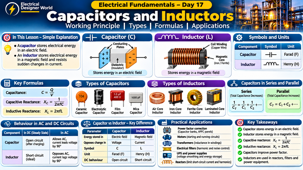
Introduction
Resistance, reactance and impedance are three fundamental concepts in electrical engineering.
When we study DC circuits, resistance is commonly used to calculate current. However, AC circuits behave differently because they may contain resistors, inductors and capacitors.
These components create different types of opposition to current flow. Understanding their behaviour helps electrical engineers analyse AC circuits and perform practical electrical calculations.
In this lesson, we will learn:
- What resistance means and how to calculate it.
- What inductive and capacitive reactance mean.
- What impedance is and how to calculate it.
- The difference between resistance, reactance and impedance.
- What an impedance triangle represents.
- How these concepts are used in industrial electrical systems.
1. What Is Resistance?
Resistance is the opposition offered by a material or electrical component to the flow of electric current.
Think about water flowing through a narrow pipe. The narrow pipe restricts the flow of water. Similarly, resistance restricts the flow of electric current.
Resistance is represented by the letter R and measured in ohms (Ω).
Formula for Resistance
Resistance = Voltage ÷ Current
R = V ÷ I
Where:
- R = Resistance in ohms (Ω)
- V = Voltage in volts (V)
- I = Current in amperes (A)
Practical Example
Suppose a resistor is connected to a 230 V supply and draws 5 A current.
Given:
- Voltage = 230 V
- Current = 5 A
Calculation:
R = 230 ÷ 5
R = 46 Ω
Therefore, the resistance is 46 ohms.
Factors Affecting Resistance
Resistance depends on several factors:
- Material: Copper has low resistance, while materials such as nichrome have higher resistance.
- Length: A longer conductor generally has higher resistance.
- Cross-sectional area: A thicker conductor generally has lower resistance.
- Temperature: For most metallic conductors, resistance increases as temperature rises.
Where Is Resistance Used?
Resistance is found in:
- Electrical heaters.
- Lighting circuits.
- Resistors in electronic equipment.
- Motor windings.
- Cables and conductors.
- Electrical control panels.
2. What Is Reactance?
Reactance is the opposition to alternating current caused by inductors and capacitors.
Unlike resistance, reactance depends on the frequency of the AC supply.
Reactance is represented by X and measured in ohms (Ω).
There are two main types:
- Inductive reactance.
- Capacitive reactance.
A. What Is Inductive Reactance?
Inductive reactance is the opposition to alternating current caused by an inductor or coil.
When AC flows through a coil, a changing magnetic field is produced. This changing magnetic field induces a voltage that opposes the change in current.
This opposition is called inductive reactance.
It is represented by XL.
Formula:
XL = 2 × π × f × L
Where:
- XL = Inductive reactance in ohms (Ω).
- π = 3.1416.
- f = Frequency in hertz (Hz).
- L = Inductance in henry (H).
Important point: Inductive reactance increases when frequency increases.
This means an inductor offers greater opposition to AC at higher frequencies, assuming its inductance remains constant.
Inductive Reactance Calculation
Suppose:
- Frequency = 50 Hz.
- Inductance = 0.1 H.
XL = 2 × 3.1416 × 50 × 0.1
XL = 31.42 Ω approximately.
Therefore, the inductive reactance is approximately 31.42 ohms.
B. What Is Capacitive Reactance?
Capacitive reactance is the opposition offered by a capacitor to alternating current.
A capacitor stores and releases energy in an electric field. Its opposition to AC depends on the supply frequency and capacitance.
It is represented by XC.
Formula:
XC = 1 ÷ (2 × π × f × C)
Where:
- XC = Capacitive reactance in ohms (Ω).
- π = 3.1416.
- f = Frequency in hertz (Hz).
- C = Capacitance in farads (F).
Important point: Capacitive reactance decreases when frequency increases.
This means a capacitor offers less opposition to AC at higher frequencies, assuming its capacitance remains constant.
Capacitive Reactance Calculation
Suppose:
- Frequency = 50 Hz.
- Capacitance = 100 µF.
- Capacitance in farads = 0.0001 F.
XC = 1 ÷ (2 × 3.1416 × 50 × 0.0001)
XC = 31.83 Ω approximately.
Therefore, the capacitive reactance is approximately 31.83 ohms.
3. What Is Impedance?
Impedance is the total opposition offered to alternating current in an electrical circuit.
It combines two components:
- Resistance.
- Reactance.
Impedance is represented by the letter Z and measured in ohms (Ω).
In simple terms:
- Resistance opposes current flow.
- Reactance represents the opposition caused by inductors and capacitors in AC circuits.
- Impedance represents their combined effect.
Resistance and reactance must be combined using their phase relationship. They cannot always be added as ordinary numbers.
Formula for Impedance in a Series RLC Circuit
For a series circuit containing resistance, inductance and capacitance:
Z = √[R² + (XL − XC)²]
Where:
- Z = Impedance in ohms.
- R = Resistance in ohms.
- XL = Inductive reactance in ohms.
- XC = Capacitive reactance in ohms.
This formula calculates the magnitude of impedance in a series RLC circuit.
Impedance Calculation – Practical Example
Consider a series AC circuit with:
- Resistance (R) = 30 Ω.
- Inductive reactance (XL) = 50 Ω.
- Capacitive reactance (XC) = 10 Ω.
Step 1: Calculate net reactance.
Net Reactance = XL − XC
Net Reactance = 50 − 10
Net Reactance = 40 Ω.
Step 2: Calculate impedance.
Z = √[R² + (XL − XC)²]
Z = √[30² + 40²]
Z = √[900 + 1600]
Z = √2500
Z = 50 Ω.
Therefore, the total impedance of the circuit is 50 ohms.
Step 3: Calculate current if the supply voltage is 230 V.
Using AC Ohm’s Law:
I = V ÷ Z
I = 230 ÷ 50
I = 4.6 A.
The circuit current is 4.6 amperes.
Since XL is greater than XC, the circuit is net inductive and the current lags the supply voltage.
4. Difference Between Resistance, Reactance and Impedance
| Parameter | Resistance | Reactance | Impedance |
|---|---|---|---|
| Meaning | Opposition to current flow | Opposition to AC due to inductors and capacitors | Combined opposition in an AC circuit |
| Symbol | R | X | Z |
| Unit | Ohm (Ω) | Ohm (Ω) | Ohm (Ω) |
| Frequency dependence | Ideally independent of frequency | Depends on frequency | Depends on circuit components and frequency |
| Associated components | Resistors and conductors | Inductors and capacitors | All practical circuit components |
| Phase relationship | Voltage and current are in phase for a pure resistor | Voltage and current have a phase difference | Depends on the circuit |
| Application | Heaters and resistive loads | Motors, coils and capacitors | AC circuit calculations |
5. What Is an Impedance Triangle?
An impedance triangle is a graphical representation of the relationship between resistance, reactance and impedance in a series AC circuit.
It is drawn as a right-angled triangle.
- Horizontal side = Resistance (R).
- Vertical side = Net reactance (XL − XC).
- Hypotenuse = Impedance (Z).
The impedance triangle helps engineers understand the relationship between these three electrical quantities.
Important Formulas
Z = √[R² + X²]
X = XL − XC
tan φ = X ÷ R
Power Factor = cos φ = R ÷ Z
Here, φ represents the phase angle between voltage and current for a sinusoidal series circuit.
If XL is greater than XC, the circuit is inductive.
If XC is greater than XL, the circuit is capacitive.
If XL equals XC, the net reactance is zero.
6. How Resistance, Reactance and Impedance Behave in AC and DC Circuits
Their behaviour depends on the type of supply and the components used.
| Component | DC steady-state behaviour (ideal) | AC behaviour |
|---|---|---|
| Resistor | Offers resistance | Offers resistance |
| Inductor | Acts approximately as a short circuit | Produces inductive reactance |
| Capacitor | Acts as an open circuit after charging | Produces capacitive reactance |
In a pure resistive AC circuit, voltage and current are in phase.
In a pure inductive AC circuit, current lags voltage by 90 degrees.
In a pure capacitive AC circuit, current leads voltage by 90 degrees.
These phase relationships describe ideal components. Real equipment also has losses and additional resistance.
7. Relationship Between Impedance and Electrical Current
Impedance determines how much current flows through an AC circuit for a given applied voltage.
The AC form of Ohm’s Law is:
I = V ÷ Z
Where:
- I = RMS current in amperes.
- V = RMS voltage in volts.
- Z = Impedance magnitude in ohms.
Practical Example
Supply voltage = 230 V.
Circuit impedance = 46 Ω.
Current = 230 ÷ 46.
Current = 5 A.
If impedance increases while the supply voltage remains constant, the current decreases.
This relationship is important when analysing electrical loads and selecting suitable circuit components.
8. What Is the Relationship Between Impedance and Power Factor?
Impedance and power factor are closely related in sinusoidal AC circuits.
For a series circuit:
Power Factor = R ÷ Z
For example:
- Resistance = 30 Ω.
- Impedance = 50 Ω.
Power Factor = 30 ÷ 50.
Power Factor = 0.6.
This is a lagging power factor if the net reactance is inductive, and a leading power factor if the net reactance is capacitive.
Power factor is important because it affects the current required to deliver a given amount of real power.
To understand this concept in more detail, read our article on Power Factor Explained: kW, kVA and kVAR in Simple English.
9. What Is Electrical Resonance?
Electrical resonance occurs in an AC circuit when inductive reactance and capacitive reactance become equal.
XL = XC
At this condition, the net reactance is zero.
For an ideal series RLC circuit:
Z = R
This means the circuit impedance is at its minimum value, and the current is at its maximum value for a fixed supply voltage.
Resonant Frequency Formula
f₀ = 1 ÷ (2 × π × √(L × C))
Where:
- f₀ = Resonant frequency in hertz.
- L = Inductance in henry.
- C = Capacitance in farads.
Resonance is used in tuning circuits, filters and other electrical and electronic applications.
In practical installations, resonance and harmonics must be considered carefully when selecting capacitor banks and filters.
10. Practical Applications in Industrial Electrical Systems
Resistance, reactance and impedance are important in electrical engineering and EPC projects.
1. Electrical Motors
Motor windings have resistance and inductive reactance. Impedance influences motor current and electrical performance.
2. Transformers
Transformer windings have resistance and leakage reactance. Transformer impedance is important when calculating voltage drop and short-circuit current.
3. Cable Sizing
Cable resistance and reactance contribute to voltage drop. Engineers consider these parameters when selecting cables for electrical installations.
4. Short-Circuit Calculations
The impedance of transformers, cables, generators and other equipment affects the prospective fault current in an electrical system.
5. Capacitor Banks
Capacitors are used for power factor correction. Their reactance and interaction with system inductance must be considered during design.
6. Electrical Filters
Inductors and capacitors are used in filters to control selected frequencies and reduce unwanted harmonic components.
7. Switchgear and Protection
System impedance helps engineers estimate fault levels and check whether switchgear and protective devices have suitable ratings.
11. Why Is This Important for EPC Electrical Design?
In an EPC project, engineers work with electrical calculations, equipment specifications, vendor documents and electrical drawings.
Understanding resistance, reactance and impedance helps engineers:
- Calculate voltage drop in power cables.
- Understand transformer impedance values.
- Estimate short-circuit current.
- Analyse motor starting and running conditions.
- Understand power factor and reactive power.
- Review electrical equipment ratings.
- Understand the behaviour of AC distribution systems.
These concepts form an important foundation before learning advanced electrical design calculations.
For additional learning, explore our articles on Single-Phase vs Three-Phase Electricity Explained and Star and Delta Connections Explained.
12. Frequently Asked Questions
1. What is the difference between resistance and impedance?
Resistance is the opposition to current flow. Impedance is the combined effect of resistance and reactance in an AC circuit.
2. Is reactance measured in ohms?
Yes. Both inductive reactance and capacitive reactance are measured in ohms (Ω).
3. Does reactance depend on frequency?
Yes. Inductive reactance increases with frequency, while capacitive reactance decreases with frequency.
4. Can impedance exist in a DC circuit?
Yes. In steady-state ideal DC circuits, capacitors and inductors behave differently than they do during AC operation. For a simple resistive DC circuit, impedance reduces to resistance.
5. Why is impedance important in electrical systems?
Impedance helps engineers calculate AC current, voltage drop, fault current and the electrical behaviour of equipment.
6. What happens when inductive reactance equals capacitive reactance?
The circuit reaches resonance. In an ideal series RLC circuit, net reactance becomes zero and impedance equals resistance.
7. What is the unit of impedance?
The unit of impedance is the ohm (Ω).
13. Practice Questions
Test your understanding of resistance, reactance and impedance.
Question 1: What is the unit of resistance?
A. Volt
B. Ampere
C. Ohm
D. Watt
Question 2: Which component produces inductive reactance?
A. Resistor
B. Inductor
C. Fuse
D. Circuit breaker
Question 3: What happens to inductive reactance when frequency increases?
A. It decreases
B. It increases
C. It becomes zero
D. It remains constant
Question 4: What is the formula for impedance in a series RLC circuit?
A. Z = R + XL + XC
B. Z = √[R² + (XL − XC)²]
C. Z = V × I
D. Z = V ÷ R
Question 5: If resistance is 30 Ω and net reactance is 40 Ω, what is the impedance?
A. 40 Ω
B. 50 Ω
C. 60 Ω
D. 70 Ω
Answers
- C — Ohm.
- B — Inductor.
- B — It increases.
- B — Z = √[R² + (XL − XC)²].
- B — 50 Ω.
For a deeper technical explanation of resistance, reactance and impedance in AC circuits, refer to All About Circuits – Review of R, X and Z.
To explore more topics related to AC circuit analysis, inductors, capacitors and resonance, visit the All About Circuits – Alternating Current Textbook.
Conclusion
Resistance, reactance and impedance are fundamental concepts in electrical engineering.
Resistance opposes current flow, reactance represents the opposition caused by inductors and capacitors in AC circuits, and impedance combines resistance and reactance to determine the total opposition to alternating current.
Understanding these concepts helps electrical engineers analyse motors, transformers, cables, capacitor banks, filters and power distribution systems.
Practise the formulas and numerical examples to build a strong foundation in AC circuit analysis.
Continue learning with Electrical Designer World and strengthen your electrical engineering fundamentals step by step.
Continue the 30-Day Electrical Fundamentals Course
This lesson is part of the Electrical Fundamentals – Zero to Advanced course on Electrical Designer World.
- Previous lesson: Day 17 – Capacitors and Inductors.
- Current lesson: Day 18 – Resistance, Reactance and Impedance.
- Next lesson: Day 19 – AC Circuits and Impedance Calculations.
Explore more electrical engineering lessons and practical explanations at Electrical Designer World.