
Transformers Explained: Working Principle, Types, Parts, Formulas and Applications
Day 19 – Electrical Fundamentals: 30-Day Learning Course
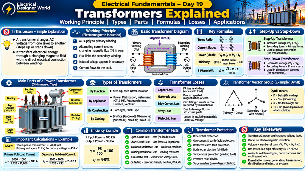
Table of Contents
Simple Explanation
Think of a transformer as an electrical device that changes voltage from one level to another. It can increase voltage or decrease voltage without directly connecting the input and output windings electrically.
For example, electricity generated at a power station is stepped up to a high voltage for long-distance transmission. Near consumers, transformers step down the voltage to levels suitable for homes, offices and industries.
Transformers are essential in electrical power systems because they help transfer electrical energy efficiently and safely between different voltage levels.
Introduction
A transformer is one of the most important pieces of equipment in an electrical power system.
Transformers are used in power generation stations, transmission substations, distribution networks, industrial plants, commercial buildings and electrical control systems.
They work on the principle of electromagnetic induction. A transformer transfers electrical energy from one AC circuit to another through a changing magnetic field.
In this lesson, we will understand:
- What a transformer is.
- How a transformer works.
- The primary and secondary windings.
- Important transformer parts.
- Step-up and step-down transformers.
- Different types of transformers.
- Transformer formulas and calculations.
- Transformer losses and efficiency.
- Transformer cooling methods.
- Transformer tests and protection.
- Practical applications in EPC electrical projects.
1. What Is a Transformer?
A transformer is a static electrical device that transfers electrical energy from one AC circuit to another through electromagnetic induction, usually changing the voltage and current levels.
It mainly consists of:
- Primary winding.
- Secondary winding.
- Magnetic core.
- Insulation system.
- Cooling arrangement, depending on the transformer design.
The primary winding receives electrical energy from the supply. The secondary winding delivers electrical energy to the connected load.
There is no direct electrical connection between the primary and secondary windings in a conventional two-winding transformer. Energy is transferred through magnetic coupling.
Important: A conventional transformer requires changing magnetic flux to induce voltage. Therefore, it cannot continuously transfer power using a steady DC supply in the same way it does with AC. Applying DC directly to a transformer designed for AC can cause excessive current and overheating.
2. Working Principle of a Transformer
A transformer works on the principle of mutual electromagnetic induction.
When an alternating voltage is applied to the primary winding, an alternating current flows through it.
This current produces a changing magnetic flux in the transformer core.
The changing magnetic flux links with the secondary winding and induces an electromotive force (EMF) in it.
When a load is connected to the secondary winding, current flows through the load.
Step-by-Step Working
Step 1: AC supply is applied
An AC voltage is connected to the primary winding.
Step 2: Magnetic flux is produced
The alternating current in the primary winding creates a changing magnetic field in the core.
Step 3: Magnetic flux links the secondary winding
The magnetic core provides a path for the changing magnetic flux to link the secondary winding.
Step 4: Voltage is induced
According to Faraday’s law of electromagnetic induction, the changing magnetic flux induces a voltage in the secondary winding.
Step 5: Current flows to the load
When a load is connected to the secondary side, current flows and electrical power is delivered to the load.
This is how a transformer transfers electrical energy from one circuit to another.
3. Main Parts of a Transformer
A power transformer contains several important components. Their arrangement depends on the transformer rating, voltage level, construction and cooling design.
1. Magnetic Core
The magnetic core provides a low-reluctance path for magnetic flux.
It is generally made from laminated electrical steel. Laminations help reduce eddy current losses.
2. Primary Winding
The primary winding is connected to the input AC supply.
It produces the alternating magnetic flux required for transformer operation.
3. Secondary Winding
The secondary winding receives magnetic flux from the core and develops an induced voltage.
It supplies electrical energy to the connected load.
4. Transformer Oil
In oil-immersed transformers, insulating oil provides electrical insulation and helps transfer heat away from the core and windings.
5. Main Tank
The main tank houses the core, windings and insulating oil in an oil-immersed transformer.
6. Conservator Tank
A conservator is an oil expansion chamber used in many oil-immersed transformers.
It accommodates changes in oil volume caused by temperature variations.
7. Radiators
Radiators help dissipate heat from the transformer oil into the surrounding air.
8. Bushings
Bushings provide insulated passages for electrical conductors to enter or leave the transformer tank.
9. Breather
A breather is used in certain conservator-type transformer designs to help control moisture entering through the air exchange system.
It commonly contains silica gel.
10. Tap Changer
A tap changer changes the effective turns ratio to adjust the transformer voltage.
There are two common types:
- Off-circuit tap changer: The transformer must be isolated from the supply before changing the tap.
- On-load tap changer (OLTC): Changes the tap while the transformer remains energised and supplying load, using a specialised switching arrangement.
11. Buchholz Relay
A Buchholz relay is used in many conservator-type oil-immersed transformers.
It detects certain internal faults that cause gas accumulation or oil movement between the main tank and conservator.
12. Pressure Relief Device
A pressure relief device releases excessive internal pressure to help protect the transformer tank.
Not every transformer uses all these components. Dry-type transformers, for example, do not have an oil tank, conservator or oil radiators.
4. How Does a Transformer Change Voltage?
The voltage transformation depends mainly on the number of turns in the primary and secondary windings.
The relationship is called the transformer turns ratio.
Transformer Turns Ratio Formula
Vp / Vs = Np / Ns
Where:
- Vp = Primary voltage.
- Vs = Secondary voltage.
- Np = Number of primary winding turns.
- Ns = Number of secondary winding turns.
For an ideal transformer, voltage is proportional to the number of winding turns.
Example
Suppose:
- Primary voltage = 11,000 V.
- Primary turns = 1,000.
- Secondary turns = 100.
Using the formula:
Vp / Vs = Np / Ns
11,000 / Vs = 1,000 / 100
11,000 / Vs = 10
Vs = 11,000 / 10
Secondary voltage = 1,100 V.
Therefore, the transformer reduces the voltage from 11,000 V to 1,100 V.
5. Types of Transformers Based on Voltage Transformation
Transformers can be classified according to their function.
A. Step-Up Transformer
A step-up transformer increases the secondary voltage compared with the primary voltage.
In this transformer:
- Secondary winding has more turns than the primary winding.
- Output voltage is higher.
- Output current is lower for approximately the same power, ignoring losses.
Application: Power generation stations use step-up transformers to increase voltage before transmitting electricity over long distances.
B. Step-Down Transformer
A step-down transformer decreases the secondary voltage compared with the primary voltage.
In this transformer:
- Secondary winding has fewer turns than the primary winding.
- Output voltage is lower.
- Output current is higher for approximately the same power, ignoring losses.
Application: Distribution substations use step-down transformers to provide lower voltages to consumers and industrial facilities.
C. Isolation Transformer
An isolation transformer provides electrical separation between two circuits.
In a conventional 1:1 isolation transformer, the primary and secondary voltages are approximately equal.
It is used in electrical testing, maintenance facilities and applications requiring electrical isolation.
6. Types of Transformers Based on Application
1. Power Transformer
Power transformers are generally used in generation stations and transmission substations.
They transfer large amounts of electrical power between high-voltage systems.
2. Distribution Transformer
Distribution transformers reduce distribution voltage to levels suitable for end users.
They are commonly installed in local distribution networks, commercial buildings and industrial facilities.
3. Instrument Transformer
Instrument transformers are used for measurement and protection.
Two important types are:
Current Transformer (CT):
A current transformer reduces a high current to a smaller standard secondary current suitable for meters and protective relays.
Potential Transformer (PT) / Voltage Transformer (VT):
A potential transformer reduces high voltage to a lower standard voltage suitable for measurement and protection.
4. Autotransformer
An autotransformer uses a single winding with a portion of the winding shared by the input and output circuits.
It is used in applications such as voltage regulation and certain motor starting arrangements.
Unlike a conventional two-winding transformer, it does not provide complete electrical isolation between input and output.
5. Furnace Transformer
Furnace transformers are designed for industrial furnace applications and may supply high currents at relatively low voltages.
6. Rectifier Transformer
Rectifier transformers are used in systems that supply power to rectifiers, such as industrial DC power supplies and electrochemical processes.
7. Transformer Types Based on Construction
1. Core-Type Transformer
In a core-type transformer, the windings are arranged around the core limbs.
2. Shell-Type Transformer
In a shell-type transformer, the core surrounds a substantial portion of the windings.
Both designs are used in transformer engineering, with selection depending on electrical, thermal, mechanical and manufacturing requirements.
8. Transformer Types Based on Cooling
Transformers generate heat because of electrical and magnetic losses. Cooling systems remove this heat and help maintain acceptable operating temperatures.
Common Cooling Arrangements
1. Dry-Type Air-Cooled Transformer
Uses air to cool the core and windings. It is often selected for indoor installations where oil-filled equipment is not preferred.
2. Oil-Immersed Natural Air-Cooled Transformer
Oil circulates naturally inside the transformer, while external air removes heat from the radiators or tank.
3. Oil-Immersed Forced Air-Cooled Transformer
Fans force air over the radiators to improve heat dissipation.
4. Oil-Immersed Forced Oil-Cooled Transformer
Pumps circulate oil through a cooling arrangement to remove heat.
Cooling designations and arrangements vary by transformer design and applicable standards. Always refer to the manufacturer’s documentation for the actual cooling classification.
9. Important Transformer Formulas
The following formulas are commonly used to understand transformer operation.
1. Voltage Ratio
Vp / Vs = Np / Ns
2. Current Ratio for an Ideal Transformer
Ip / Is = Ns / Np
Where:
- Ip = Primary current.
- Is = Secondary current.
For an ideal transformer, current changes inversely with voltage.
3. Input and Output Power for an Ideal Transformer
Input Power = Output Power
Vp × Ip = Vs × Is
This assumes an ideal transformer with no losses.
In a real transformer, output power is lower than input power because of losses.
4. Transformer Efficiency
Efficiency (%) = (Output Power ÷ Input Power) × 100
A transformer with lower losses has higher efficiency.
5. Three-Phase Transformer Apparent Power
For a balanced three-phase transformer:
S (kVA) = √3 × Line Voltage × Line Current ÷ 1000
Using the approximate value of √3:
S (kVA) = 1.732 × V × I ÷ 1000
Where:
- S = Apparent power in kVA.
- V = Line-to-line voltage in volts.
- I = Line current in amperes.
10. Practical Transformer Calculation – 2000 kVA Transformer
Let us understand how to calculate the full-load current of an industrial transformer.
Assume a three-phase transformer has the following rating:
- Transformer rating = 2000 kVA.
- Primary voltage = 11 kV.
- Secondary voltage = 433 V.
Step 1: Calculate Primary Full-Load Current
Formula:
I = kVA × 1000 ÷ (1.732 × Voltage)
Substitute the values:
Primary Current = 2000 × 1000 ÷ (1.732 × 11,000)
Primary Current ≈ 105 A.
Step 2: Calculate Secondary Full-Load Current
Secondary Current = 2000 × 1000 ÷ (1.732 × 433)
Secondary Current ≈ 2,667 A.
Calculation Summary
| Parameter | Value |
|---|---|
| Transformer rating | 2000 kVA |
| Primary voltage | 11 kV |
| Secondary voltage | 433 V |
| Primary full-load current | Approximately 105 A |
| Secondary full-load current | Approximately 2,667 A |
This example shows that when transformer voltage decreases, the current increases for approximately the same apparent power.
These are calculated full-load current values. Actual operating current depends on the load, power factor, voltage and transformer operating conditions.
11. What Are Transformer Losses?
A transformer is highly efficient, but it is not 100% efficient in practical operation.
Some electrical energy is lost as heat and other forms of energy.
The major transformer losses are:
1. Copper Loss
Copper loss occurs because the primary and secondary windings have electrical resistance.
Formula:
Copper Loss = I² × R
Where:
- I = Winding current.
- R = Winding resistance.
Copper losses vary with load current.
2. Hysteresis Loss
Hysteresis loss occurs in the magnetic core due to repeated magnetisation and demagnetisation during AC operation.
3. Eddy Current Loss
Eddy currents are circulating currents induced inside the transformer core.
They produce heat and reduce efficiency.
Laminated core construction helps reduce eddy current losses.
4. Stray Losses
Stray losses occur due to leakage magnetic flux inducing currents in structural and other conducting parts.
5. Dielectric Loss
Dielectric losses occur in insulating materials subjected to alternating electric fields.
12. Transformer Efficiency
Transformer efficiency indicates how effectively the transformer converts input electrical power into output electrical power.
Formula:
Efficiency (%) = (Output Power ÷ Input Power) × 100
Example
Suppose:
- Input power = 100 kW.
- Output power = 98 kW.
Efficiency = (98 ÷ 100) × 100
Efficiency = 98%.
This means 98% of the input power is delivered as output power, while the remaining 2% represents losses under the stated operating condition.
13. What Is Transformer Impedance?
Transformer impedance represents the opposition to alternating current within the transformer.
It is commonly expressed as a percentage called percentage impedance or impedance voltage.
Transformer impedance is important for:
- Calculating short-circuit current.
- Selecting circuit breakers.
- Coordinating protection systems.
- Understanding voltage regulation.
- Evaluating parallel transformer operation.
A transformer with lower percentage impedance generally allows a higher prospective short-circuit current, assuming the same rating and system conditions.
The actual fault current also depends on the upstream network impedance and other circuit impedances.
14. Transformer Vector Group
A transformer vector group describes the winding connections and the phase displacement between primary and secondary voltages.
Common connection symbols include:
- Y – Star-connected winding.
- D – Delta-connected winding.
- Z – Zigzag-connected winding.
- N – Neutral brought out.
For example, Dyn11 indicates:
- D = High-voltage winding connected in delta.
- y = Low-voltage winding connected in star.
- n = Neutral terminal brought out.
- 11 = Clock notation representing a 30-degree phase displacement according to the standard convention.
Vector group information is important when selecting transformers for parallel operation and coordinating three-phase electrical systems.
Transformers intended for parallel operation must satisfy important compatibility conditions, including voltage ratio, polarity, phase sequence, vector group or phase displacement, and suitable impedance characteristics.
15. Transformer Tests
Transformer testing helps verify electrical performance, insulation condition and operational reliability.
Common tests include:
1. Open-Circuit Test
The open-circuit test is generally performed to determine core or no-load losses and related no-load parameters.
2. Short-Circuit Test
The short-circuit test is generally used to determine load losses and equivalent impedance parameters.
3. Insulation Resistance Test
This test evaluates insulation resistance between windings and between windings and earth, using an appropriate test procedure.
4. Winding Resistance Test
This test measures the resistance of transformer windings and helps identify abnormalities such as poor connections or winding problems.
5. Transformer Turns Ratio Test
This test checks whether the winding turns ratio matches the expected design or nameplate value.
6. Oil Testing
For oil-filled transformers, oil tests may evaluate moisture, dielectric strength and other condition indicators. Dissolved gas analysis may also be used to identify possible internal faults.
Testing requirements depend on transformer type, voltage rating, project specifications and applicable standards.
16. Transformer Protection
Transformers require suitable protection against electrical faults and abnormal operating conditions.
Common protection arrangements include:
- Differential protection.
- Overcurrent protection.
- Earth-fault protection.
- Restricted earth-fault protection.
- Buchholz protection, where applicable.
- Winding and oil temperature protection.
- Pressure relief protection.
- Surge arresters for suitable overvoltage protection.
The protection scheme depends on transformer capacity, voltage level, earthing arrangement, installation and system design.
17. Transformer Applications in EPC Electrical Projects
Transformers are essential equipment in industrial and infrastructure projects.
1. Power Distribution
Transformers reduce high distribution voltages to suitable utilisation voltages for buildings and industrial loads.
2. Motor Control Centres (MCC)
Transformers may supply the required voltage levels to motor control systems and associated equipment.
3. Lighting Distribution
Lighting transformers or distribution transformers may be used to supply suitable voltage levels to lighting panels and lighting systems.
4. UPS Systems
Transformers may be used in UPS systems for isolation, voltage matching or other functions depending on the UPS design.
5. Instrumentation and Protection
CTs and VTs provide scaled electrical quantities to meters, monitoring systems and protective relays.
6. Industrial Processes
Special transformers are used in welding, furnaces, rectifiers and other industrial applications.
18. What Should an Electrical Engineer Check in a Transformer Datasheet?
When reviewing transformer vendor documents in an EPC project, pay attention to the following details:
| Parameter | What to Check |
|---|---|
| Rated capacity | Transformer rating in kVA or MVA |
| Primary voltage | Rated input voltage |
| Secondary voltage | Rated output voltage |
| Frequency | 50 Hz or specified project frequency |
| Phase | Single-phase or three-phase |
| Vector group | Winding connection and phase displacement |
| Impedance | Percentage impedance |
| Cooling | Cooling arrangement |
| Tap changer | Type, range and tapping positions |
| Temperature rise | Permitted temperature rise |
| Insulation level | Specified insulation withstand levels |
| Losses | No-load and load losses |
| Accessories | Required protection and monitoring accessories |
| Standards | Applicable project and technical standards |
The approved datasheet, technical specification, drawings and applicable standards should always be used for final design and equipment selection.
19. Electrical Safety Around Transformers
Transformers operate at potentially dangerous voltage and current levels. Their terminals, bushings and internal components can present serious electrical hazards.
Important safety precautions include:
- Only qualified and authorised personnel should operate or maintain transformers.
- Isolate all possible sources of supply before maintenance.
- Follow lockout/tagout (LOTO) procedures.
- Verify absence of voltage using approved equipment.
- Apply earthing and discharge procedures as required by the approved safety method.
- Follow the manufacturer’s maintenance instructions.
- Never approach exposed live terminals.
- Maintain appropriate electrical clearances.
- Use suitable PPE and follow site electrical safety procedures.
Even after isolation, stored electrical energy and induced voltages may create hazards. Always follow the approved site safety procedure.
20. Frequently Asked Questions
1. What is the main function of a transformer?
The main function of a transformer is to transfer electrical energy between AC circuits and change voltage and current levels through electromagnetic induction.
2. Can a transformer work on DC supply?
A conventional transformer cannot continuously transfer power using steady DC because steady DC does not produce changing magnetic flux. Applying DC directly can cause excessive current and overheating.
3. What is the difference between a step-up and a step-down transformer?
A step-up transformer increases voltage, while a step-down transformer decreases voltage.
4. What is the function of a transformer core?
The transformer core provides a magnetic path for flux linking the primary and secondary windings.
5. Why are transformer cores laminated?
Laminations help reduce eddy current losses in the magnetic core.
6. What is transformer kVA?
Transformer capacity is commonly expressed in kVA because the transformer is rated based on voltage and current, while its real power output in kW also depends on the load power factor.
7. What is a transformer vector group?
A vector group identifies the winding connection and phase displacement between the primary and secondary windings.
8. Why is transformer impedance important?
Transformer impedance is important for short-circuit current calculations, protection selection, voltage regulation and parallel operation.
9. What is a Buchholz relay?
A Buchholz relay is a protective device used in many conservator-type oil-filled transformers to detect certain internal faults through gas accumulation or oil movement.
10. What is the difference between a power transformer and a distribution transformer?
Power transformers are commonly used in generation and transmission systems, while distribution transformers reduce voltage for local distribution and end users.
21. Practice Questions
Test your understanding of transformers.
Question 1: What is the working principle of a transformer?
A. Electrostatic induction
B. Electromagnetic induction
C. Chemical reaction
D. Mechanical friction
Question 2: Which winding is connected to the input supply?
A. Secondary winding
B. Primary winding
C. Tertiary winding
D. Earthing winding
Question 3: What happens in a step-up transformer?
A. Voltage decreases
B. Voltage increases
C. Frequency increases
D. Frequency decreases
Question 4: Which component provides the magnetic path for flux?
A. Conservator
B. Bushing
C. Core
D. Radiator
Question 5: Which loss is caused by winding resistance?
A. Hysteresis loss
B. Copper loss
C. Eddy current loss
D. Dielectric loss
Question 6: What does a transformer vector group indicate?
A. Transformer colour
B. Winding connection and phase displacement
C. Oil quantity
D. Core weight
Answers
- B – Electromagnetic induction.
- B – Primary winding.
- B – Voltage increases.
- C – Core.
- B – Copper loss.
- B – Winding connection and phase displacement.
external referance:
- 1. OpenStax – Transformer Working Principle
- To understand the working principle of transformers, voltage transformation and the relationship between primary and secondary windings, refer to OpenStax – Transformers.
- 2. Bharat Skills – Transformers and Their Types
- For additional technical learning about transformer construction, turns ratio, types, losses and testing, refer to the Bharat Skills Electrical Textbook.
- 3. Bureau of Energy Efficiency – Electrical Systems
- For additional information about energy-efficient electrical systems and transformer-related energy considerations, explore the Bureau of Energy Efficiency.
Conclusion
Transformers are essential components in electrical power generation, transmission, distribution and industrial installations.
They work on electromagnetic induction and transfer electrical energy between AC circuits while changing voltage and current levels.
Understanding transformer working principles, parts, types, formulas, losses, cooling methods, tests and protection helps electrical engineers develop a strong foundation in electrical design.
For EPC electrical engineers, transformer knowledge is particularly important when reviewing transformer datasheets, calculating full-load current, checking impedance, understanding vector groups and coordinating protection systems.
Continue learning with Electrical Designer World and strengthen your electrical engineering fundamentals step by step.
Continue the 30-Day Electrical Fundamentals Course
1. Link to Power Factor Explained
Transformers supply electrical loads that may have different power factors. Understanding power factor helps electrical engineers calculate load current and evaluate transformer loading. Learn more in our guide on Power Factor Explained.
2. Link to Capacitors and Inductors – Day 17
Transformers work through electromagnetic induction, which is closely related to the behaviour of inductors. To understand magnetic fields, inductance and capacitors, read our guide on Capacitors and Inductors Explained.
3. Link to Resistance, Reactance and Impedance – Day 18
Transformer windings have resistance and reactance, which contribute to transformer impedance. Learn how these electrical quantities affect AC circuits in our guide on Resistance, Reactance and Impedance.
4. Link to the Electrical Designer World homepage
Explore more beginner-friendly electrical engineering lessons, practical calculations and EPC design topics at Electrical Designer World.
This lesson is part of the Electrical Fundamentals – 30-Day Learning Course.
- Previous lesson: Day 18 – Resistance, Reactance and Impedance.
- Current lesson: Day 19 – Transformers.
- Next lesson: Day 20 – Transformer Ratings, Selection and Sizing.
Explore more electrical engineering lessons at Electrical Designer World.