
Day 4: Series and Parallel Circuits – Formulas and Solved Examples
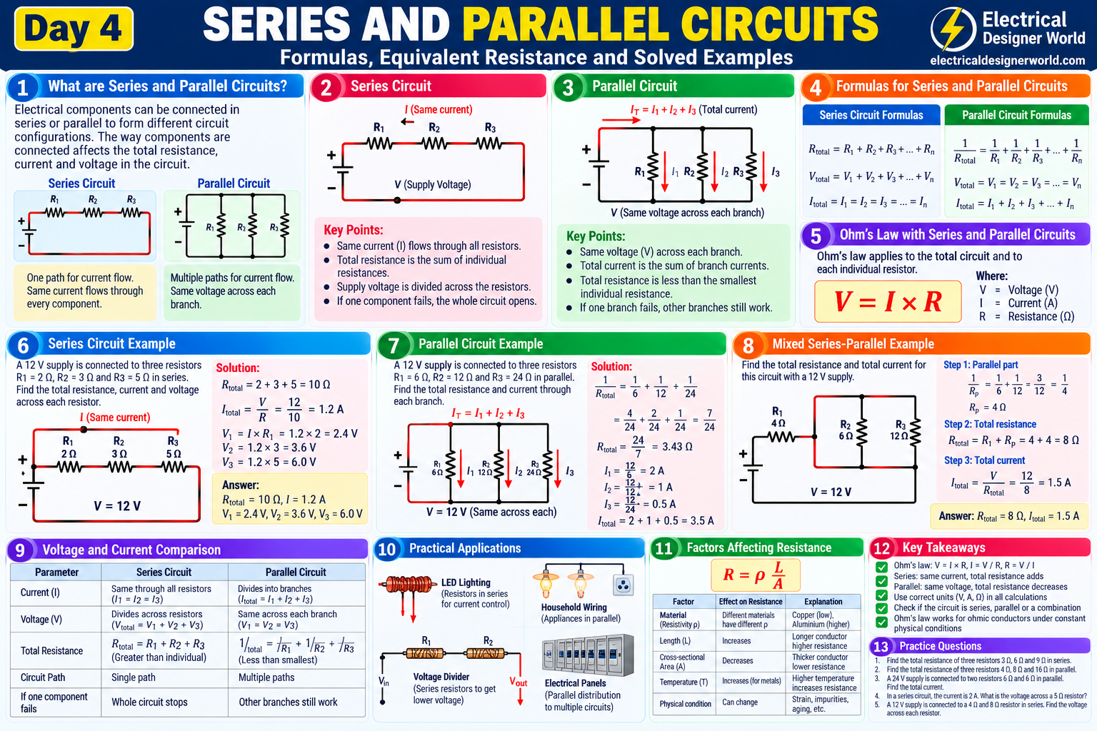
Table of Contents
Welcome to Day 4 of the Electrical Fundamentals – Zero to Advanced course at Electrical Designer World!
In Day 2, we learned about voltage, current and resistance. In Day 3, we studied Ohm’s law and how to calculate electrical quantities. Now, we will apply these concepts to understand series and parallel circuits.
Electrical components can be connected in different ways, and the arrangement affects the total resistance, current flow, and voltage distribution in a circuit.
Understanding series and parallel circuits is essential for learning electrical circuit analysis, electronic systems, electrical power, and more advanced electrical engineering concepts.
In this lesson, you will learn the definitions, formulas, circuit diagrams, differences, and practical applications of series and parallel circuits through step-by-step numerical examples.
Table of Contents
- What Are Series and Parallel Circuits?
- What Is a Series Circuit?
- Series Circuit Formulas
- Solved Series Circuit Example
- What Is a Parallel Circuit?
- Parallel Circuit Formulas
- Solved Parallel Circuit Example
- Difference Between Series and Parallel Circuits
- Mixed Series-Parallel Circuits
- Practical Applications
- Frequently Asked Questions
- Practice Questions and Answers
1. What Are Series and Parallel Circuits?
Series and parallel circuits are two common ways of connecting electrical components.
In a series circuit, components are connected along a single path, so the same current flows through each component.
In a parallel circuit, components are connected across the same two electrical nodes, creating multiple paths for current. Each branch has the same voltage across it.
These arrangements produce different electrical behaviour.
For example, a series connection increases total resistance when additional resistors are added. A parallel connection decreases total resistance when additional resistors are connected across the same two nodes.
Understanding these differences helps you calculate circuit current, voltage drops, and equivalent resistance.
2. What Is a Series Circuit?
A series circuit contains components connected one after another along a single conducting path.
Consider a circuit containing a 12 V battery and three resistors connected in series:
- R₁ = 2 Ω
- R₂ = 3 Ω
- R₃ = 5 Ω
The current has only one path through the resistors.
Characteristics of a series circuit
1. The same current flows through every resistor.
For three resistors in series:
I = I₁ = I₂ = I₃
2. The supply voltage is divided across the resistors.
The total supply voltage equals the sum of the individual voltage drops:
V = V₁ + V₂ + V₃
3. Total resistance is the sum of all resistances.
Rₜ = R₁ + R₂ + R₃
4. Adding another resistor increases total resistance.
For a fixed supply voltage, this reduces the total current.
5. An open circuit in the only current path stops the current throughout the series circuit.
This is why a break in a simple series path can cause all components in that path to stop operating.
3. Series Circuit Formulas
For resistors connected in series, use these formulas.
Total resistance
Rₜ = R₁ + R₂ + R₃ + … + Rₙ
Total current
I = V / Rₜ
Voltage across each resistor
V₁ = I × R₁
V₂ = I × R₂
V₃ = I × R₃
Example
If three resistors have values of 2 Ω, 3 Ω, and 5 Ω:
Rₜ = 2 + 3 + 5
Total resistance = 10 Ω
Remember: in a series circuit, resistances add directly.
4. Solved Series Circuit Example
A 12 V supply is connected to three resistors in series:
- R₁ = 2 Ω
- R₂ = 3 Ω
- R₃ = 5 Ω
Calculate the total resistance, circuit current, and voltage across each resistor.
Step 1: Calculate total resistance
Rₜ = R₁ + R₂ + R₃
Rₜ = 2 + 3 + 5
Rₜ = 10 Ω
Step 2: Calculate circuit current
Using Ohm’s law:
I = V / Rₜ
I = 12 / 10
I = 1.2 A
The same current flows through all three resistors.
Step 3: Calculate voltage across each resistor
For R₁:
V₁ = I × R₁
V₁ = 1.2 × 2
V₁ = 2.4 V
For R₂:
V₂ = 1.2 × 3
V₂ = 3.6 V
For R₃:
V₃ = 1.2 × 5
V₃ = 6 V
Step 4: Verify the result
V = V₁ + V₂ + V₃
V = 2.4 + 3.6 + 6
Total voltage = 12 V
The sum of the voltage drops equals the supply voltage, as expected.
5. What Is a Parallel Circuit?
A parallel circuit contains components connected across the same two nodes. Each branch provides a separate path for current.
Consider three resistors connected in parallel across a 12 V supply:
- R₁ = 6 Ω
- R₂ = 12 Ω
- R₃ = 24 Ω
Each resistor has the same voltage across it because all three are connected across the same two nodes.
Characteristics of a parallel circuit
1. The voltage is the same across every branch.
V = V₁ = V₂ = V₃
2. Total current equals the sum of branch currents.
Iₜ = I₁ + I₂ + I₃
3. Total resistance is calculated using reciprocals.
1/Rₜ = 1/R₁ + 1/R₂ + 1/R₃
4. Adding another parallel resistor decreases total resistance.
An additional branch creates another path for current.
5. An open circuit in one branch does not necessarily stop the other branches.
Other branches can continue operating if the supply and their individual paths remain intact.
This is one reason parallel connections are commonly used for household lighting and power outlets.
6. Parallel Circuit Formulas
The main formula for calculating the equivalent resistance of a parallel circuit is:
1/Rₜ = 1/R₁ + 1/R₂ + 1/R₃ + … + 1/Rₙ
For two resistors in parallel, the formula can be simplified to:
Rₜ = (R₁ × R₂) / (R₁ + R₂)
This simplified formula applies to two resistors connected across the same two nodes.
Equal resistors in parallel
If all resistors have the same resistance R, the equivalent resistance is:
Rₜ = R / n
Where n is the number of parallel resistors.
For example, three 6 Ω resistors connected in parallel have:
Rₜ = 6 / 3
Rₜ = 2 Ω
The equivalent resistance is lower than the resistance of any individual branch.
7. Solved Parallel Circuit Example
A 12 V supply is connected to three parallel resistors:
- R₁ = 6 Ω
- R₂ = 12 Ω
- R₃ = 24 Ω
Calculate the equivalent resistance, each branch current, and total current.
Step 1: Calculate equivalent resistance
1/Rₜ = 1/6 + 1/12 + 1/24
Using a common denominator:
1/Rₜ = 4/24 + 2/24 + 1/24
1/Rₜ = 7/24
Therefore:
Rₜ = 24/7
Rₜ ≈ 3.43 Ω
Step 2: Calculate current in each branch
Each branch has 12 V across it.
For R₁:
I₁ = 12 / 6
I₁ = 2 A
For R₂:
I₂ = 12 / 12
I₂ = 1 A
For R₃:
I₃ = 12 / 24
I₃ = 0.5 A
Step 3: Calculate total current
Iₜ = I₁ + I₂ + I₃
Iₜ = 2 + 1 + 0.5
Iₜ = 3.5 A
Step 4: Verify the result
Using the equivalent resistance:
Iₜ = V / Rₜ
Iₜ = 12 / (24/7)
Iₜ = 3.5 A
Both methods give the same result.
8. Difference Between Series and Parallel Circuits
| Property | Series circuit | Parallel circuit |
|---|---|---|
| Current | Same through each component | Divides among branches |
| Voltage | Divides across components | Same across each branch |
| Equivalent resistance | Sum of resistances | Reciprocal formula |
| Adding a resistor | Increases total resistance | Decreases total resistance |
| Current paths | One path | Multiple paths |
| Open component | Can stop the whole path | Other branches may continue operating |
| Common application | Voltage dividers and some LED circuits | Household wiring and distribution branches |
The rules above describe ideal circuit arrangements. Actual systems can also include wiring resistance, source impedance, switching devices, and protective components.
9. Mixed Series-Parallel Circuits
Many practical circuits contain both series and parallel connections. These are called mixed or combination circuits.
Consider a 12 V source connected to a 4 Ω resistor in series with a parallel combination of 6 Ω and 12 Ω resistors.
Step 1: Calculate the parallel resistance
Rₚ = (6 × 12) / (6 + 12)
Rₚ = 72 / 18
Rₚ = 4 Ω
Step 2: Calculate total resistance
The 4 Ω resistor is in series with the 4 Ω equivalent parallel section.
Rₜ = 4 + 4
Rₜ = 8 Ω
Step 3: Calculate total current
Iₜ = V / Rₜ
Iₜ = 12 / 8
Iₜ = 1.5 A
Step 4: Calculate voltage across the series resistor
V₁ = Iₜ × R₁
V₁ = 1.5 × 4
V₁ = 6 V
The remaining 6 V appears across the parallel section.
Step 5: Calculate branch currents
For the 6 Ω branch:
I₁ = 6 / 6 = 1 A
For the 12 Ω branch:
I₂ = 6 / 12 = 0.5 A
Total branch current:
I₁ + I₂ = 1 + 0.5 = 1.5 A
The branch currents add to the total circuit current.
A useful method for mixed circuits
- Identify resistors that are clearly in series or parallel.
- Calculate the equivalent resistance of the simplest group.
- Replace that group with its equivalent resistance.
- Repeat until one total resistance remains.
- Calculate total current using Ohm’s law.
- Work backwards to find individual voltage drops and branch currents.
This systematic method is useful for solving more complex electrical circuit problems.
10. Practical Applications of Series and Parallel Circuits
Household electrical wiring
Household appliances and lighting branches are generally connected in parallel so that each receives the appropriate supply voltage and can operate independently, subject to the installation design.
Series resistors
Series resistors are used in voltage-divider circuits and other applications where voltage must be distributed between components.
LED circuits
LED circuits may use series resistors to limit current. The required design depends on the LED characteristics, supply voltage, and circuit configuration.
Battery connections
Batteries connected in series increase the total voltage for compatible sources. Batteries connected in parallel can increase available capacity or current capability when the battery chemistry, voltage, protection, and connection arrangements are suitable.
Electrical engineering calculations
Understanding series and parallel circuits provides a foundation for analysing networks, understanding electrical loads, and progressing to more advanced electrical design calculations.
Frequently Asked Questions
1. What is a series circuit?
A series circuit connects components along a single path, so the same current flows through every component.
2. What is a parallel circuit?
A parallel circuit connects components across the same two nodes, providing separate current paths and the same voltage across each branch.
3. How do you calculate resistance in a series circuit?
Add all individual resistances: Rₜ = R₁ + R₂ + R₃ + …
4. How do you calculate resistance in a parallel circuit?
Add the reciprocals of the individual resistances and take the reciprocal of the result.
For two resistors:
Rₜ = (R₁ × R₂) / (R₁ + R₂)
5. Why is total resistance lower in a parallel circuit?
Each added branch provides another path for current. For positive resistances, adding a parallel branch reduces the equivalent resistance.
6. Which circuit has the same current through all components?
A series circuit has the same current through each component.
7. Which circuit has the same voltage across all branches?
A parallel circuit has the same voltage across each branch connected to the same two nodes.
8. What is a mixed circuit?
A mixed circuit contains both series and parallel connections. Solve it by simplifying one group at a time.
Day 4 Practice Questions
Test your understanding of series and parallel circuits.
- Three resistors of 3 Ω, 6 Ω, and 9 Ω are connected in series. Find the total resistance.
- Two resistors of 6 Ω and 3 Ω are connected in parallel. Calculate the equivalent resistance.
- A 24 V supply is connected across a 12 Ω resistor in series with a 4 Ω resistor. Find the circuit current.
- Two resistors of 6 Ω and 12 Ω are connected in parallel across a 12 V supply. Calculate each branch current and the total current.
- What happens to total resistance when another resistor is added in series?
- What happens to equivalent resistance when another resistor is added in parallel?
- Explain why household appliances are commonly connected in parallel.
- A 4 Ω resistor is connected in series with a parallel combination of 6 Ω and 12 Ω resistors. Calculate the equivalent resistance of the combination.
- A 12 V supply is connected to two 4 Ω resistors in parallel. Calculate the total current.
- State the voltage and current rules for series and parallel circuits.
Answer Key
- Rₜ = 3 + 6 + 9 = 18 Ω.
- Rₜ = (6 × 3) / (6 + 3) = 2 Ω.
- Rₜ = 12 + 4 = 16 Ω; I = 24 / 16 = 1.5 A.
- I₁ = 12 / 6 = 2 A; I₂ = 12 / 12 = 1 A; total current = 3 A.
- Total resistance increases.
- Equivalent resistance decreases.
- Parallel connections provide the same supply voltage across branches and allow appliances to operate independently.
- Parallel resistance = 4 Ω; total resistance = 4 + 4 = 8 Ω.
- Equivalent resistance = 2 Ω; total current = 12 / 2 = 6 A.
- Series: same current, voltage divides. Parallel: same voltage, current divides.
Further Reading: Series and Parallel Circuits
Explore these educational resources to deepen your understanding of electrical circuits:
- OpenStax Physics – Electric Current, Resistance, and Ohm’s Law — review the relationship between voltage, current, and resistance.
- All About Circuits – Textbook and Learning Resources — explore circuit theory, electrical components, and worked examples.
- Schneider Electric Electrical Installation Guide — learn about practical electrical installations and power distribution.
Conclusion
Series and parallel circuits are essential concepts in electrical engineering. In a series circuit, the same current flows through each component and total resistance is the sum of the individual resistances. In a parallel circuit, the voltage is the same across each branch, total current is the sum of branch currents, and equivalent resistance is calculated using reciprocals.
Once you understand these rules, you can analyse mixed circuits and solve more advanced electrical problems with confidence.
Continue learning:
- Explore the Electrical Fundamentals – 30-Day Course
- Read Day 2: Voltage, Current and Resistance
- Read Day 3: Ohm’s Law
- Day 5: Electrical Power and Energy — add the link after publishing the next lesson.
Keep learning step by step with Electrical Designer World!