
Day 2: Voltage, Current and Resistance Explained
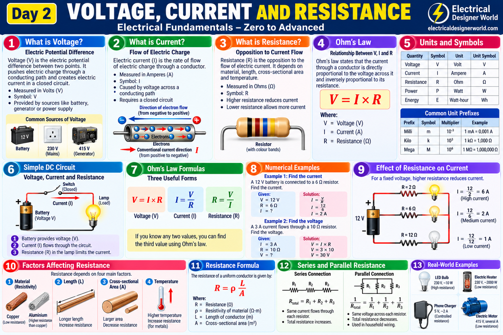
Table of Contents
Welcome to Day 2 of the Electrical Fundamentals – Zero to Advanced course at Electrical Designer World!
In Day 1, we learned about electricity, electric charge, atoms, conductors, insulators, and simple electrical circuits. Today, we will explore three of the most important concepts in electrical engineering: voltage, current and resistance.
These three electrical quantities help us understand how electrical circuits operate, how loads consume electrical energy, and how engineers calculate current in electrical systems.
If you want to learn electrical engineering from the basics, understanding voltage, current and resistance is essential before moving on to Ohm’s law, electrical power, AC circuits, transformers, and electrical equipment.
In this lesson, you will learn their meanings, units, symbols, relationships, formulas, and practical applications through simple explanations and worked examples.
Table of Contents
- What Is Voltage?
- What Is Electric Current?
- What Is Electrical Resistance?
- Difference Between Voltage, Current and Resistance
- Electrical Units and Symbols
- How Voltage, Current and Resistance Work Together
- Ohm’s Law: The Relationship Between V, I and R
- Worked Numerical Examples
- Factors Affecting Electrical Resistance
- Practical Electrical Applications
- Frequently Asked Questions
- Day 2 Practice Questions
1. What Is Voltage?
Voltage is the electric potential difference between two points in an electrical circuit. It represents the difference in electrical potential energy per unit charge between those points.
In simple terms, voltage is the electrical potential difference that can drive electric current through a suitable conducting path.
The symbol for voltage is V, and its SI unit is the volt (V).
Examples of voltage
Common examples of voltage include:
- A 1.5 V battery used in a small electronic device.
- A 12 V battery used in certain automotive and backup applications.
- A nominal 230 V single-phase supply commonly used in India.
- A nominal 415 V three-phase supply commonly used in Indian commercial and industrial installations.
Actual supply voltage and system ratings depend on the application and applicable standards.
How does voltage work?
Consider a battery connected to a lamp through conducting wires.
The battery establishes an electric potential difference between its terminals. When the circuit is closed, an electric field is established through the circuit and electric current flows.
The lamp converts electrical energy into light and heat.
Without a potential difference, there is no sustained current through a simple resistive circuit. However, a voltage can exist even when a circuit is open and no current flows.
Important points about voltage
- Voltage is measured in volts (V).
- Voltage is measured between two points.
- Voltage is commonly supplied by batteries, generators, and electrical power systems.
- Voltage is not the same as current.
- A higher voltage does not automatically mean a higher current; circuit resistance and other circuit characteristics also matter.
2. What Is Electric Current?
Electric current is the rate at which electric charge passes through a cross-section of a conductor or another component.
The symbol for current is I, and its SI unit is the ampere (A).
In simple terms, current tells us how much electric charge flows per second.
The basic formula is:
I = Q / t
Where:
- I = electric current in amperes (A)
- Q = electric charge in coulombs (C)
- t = time in seconds (s)
One ampere means one coulomb of electric charge passes a given cross-section every second.
Example of electric current
Suppose 20 coulombs of electric charge pass through a conductor in 5 seconds.
Using the formula:
I = Q / t
I = 20 / 5
I = 4 A
Therefore, the current is 4 amperes.
Conventional current versus electron flow
In metal conductors, electrons drift from the negative terminal towards the positive terminal when connected to a suitable DC source.
However, conventional current is defined in the direction that positive charge would move. In a metal conductor, conventional current therefore points opposite to electron drift.
This distinction is important when reading circuit diagrams and analysing electrical circuits.
Types of electric current
Direct current (DC): In a simple DC circuit, conventional current flows in one direction. Batteries are common DC sources.
Alternating current (AC): In an AC circuit, current changes direction periodically. AC is widely used in electricity supply systems.
We will study AC and DC in more detail in Day 10 of this course.
Important points about current
- Current is measured in amperes (A).
- Current represents the rate of flow of electric charge.
- Current depends on the applied voltage and the properties of the circuit.
- Excessive current can overheat conductors and damage electrical equipment.
- Circuit breakers and fuses help protect electrical circuits against specified overcurrent conditions.
3. What Is Electrical Resistance?
Electrical resistance is the opposition a material or component presents to electric current.
The symbol for resistance is R, and its SI unit is the ohm (Ω).
In a simple resistive circuit, increasing the resistance while keeping the voltage constant reduces the current.
For example, consider a 12 V battery connected to different resistors.
- With a 2 Ω resistor, the current is 6 A.
- With a 6 Ω resistor, the current is 2 A.
- With a 12 Ω resistor, the current is 1 A.
These values follow Ohm’s law for an ideal ohmic resistor.
What causes electrical resistance?
Resistance in a material is related to how charge carriers interact with the material’s atomic structure and other scattering mechanisms.
For a uniform conductor, resistance depends on several factors:
- The material’s electrical resistivity.
- The length of the conductor.
- The conductor’s cross-sectional area.
- Temperature and operating conditions.
Practical example
A copper conductor generally has lower resistance than an aluminium conductor of the same length and cross-sectional area at the same temperature.
A longer conductor generally has higher resistance than a shorter conductor made from the same material with the same cross-sectional area.
A larger conductor cross-sectional area generally reduces resistance.
These principles are important when studying electrical cables, voltage drop, and electrical power losses.
4. Difference Between Voltage, Current and Resistance
Voltage, current and resistance are related, but each describes a different electrical property.
| Property | Voltage | Current | Resistance |
|---|---|---|---|
| Meaning | Electric potential difference | Rate of electric charge flow | Opposition to current |
| Symbol | V | I | R |
| SI unit | Volt (V) | Ampere (A) | Ohm (Ω) |
| Common measuring instrument | Voltmeter | Ammeter | Ohmmeter |
| Basic circuit relationship | V = I × R | I = V / R | R = V / I |
| Measurement | Across two points | Through a circuit path | Across an isolated component or using a suitable measurement method |
The relationships in the table apply to an ohmic resistive component under the relevant operating conditions. Real components can have nonlinear voltage-current relationships.
A simple water-flow analogy
Imagine water flowing through a pipe.
- Voltage: Similar to a pressure difference that drives water flow.
- Current: Similar to the amount of water flowing per second.
- Resistance: Similar to restrictions that oppose the flow of water.
This analogy helps explain the basic relationship, although electrical circuits and fluid systems do not behave identically in every situation.
5. Electrical Units and Symbols
Electrical engineers use standard symbols and SI units to describe electrical quantities.
| Electrical quantity | Symbol | SI unit | Unit symbol |
|---|---|---|---|
| Voltage | V | Volt | V |
| Current | I | Ampere | A |
| Resistance | R | Ohm | Ω |
| Electric charge | Q | Coulomb | C |
| Time | t | Second | s |
| Power | P | Watt | W |
| Energy | E | Joule | J |
Electrical quantities also use prefixes to represent very small or very large values.
| Prefix | Symbol | Multiplier | Example |
|---|---|---|---|
| Milli | m | 10⁻³ | 1 mA = 0.001 A |
| Micro | µ | 10⁻⁶ | 1 µA = 0.000001 A |
| Kilo | k | 10³ | 1 kΩ = 1,000 Ω |
| Mega | M | 10⁶ | 1 MΩ = 1,000,000 Ω |
Correct use of units is essential in electrical calculations. For example, confusing milliamperes with amperes can produce a calculation error by a factor of 1,000.
6. How Voltage, Current and Resistance Work Together
Voltage, current and resistance interact according to the electrical characteristics of a circuit.
For a fixed resistance, increasing the voltage increases the current.
For a fixed voltage, increasing the resistance decreases the current.
For an ideal resistor, these relationships are described by Ohm’s law.
Consider a 12 V supply connected to a 6 Ω resistor.
The current is:
I = V / R
I = 12 / 6
I = 2 A
If the resistance changes to 12 Ω while the supply remains at 12 V:
I = 12 / 12
I = 1 A
The current decreases from 2 A to 1 A because the resistance has doubled.
This relationship is the foundation of basic electrical circuit analysis.
7. Ohm’s Law: The Relationship Between V, I and R
Ohm’s law states that the current through an ohmic conductor is directly proportional to the voltage across it when its physical conditions, including temperature, remain constant.
The formula is:
V = I × R
The formula can be rearranged to calculate any one of the three quantities when the other two are known.
Voltage formula
V = I × R
Use this formula to calculate voltage when current and resistance are known.
Current formula
I = V / R
Use this formula to calculate current when voltage and resistance are known.
Resistance formula
R = V / I
Use this formula to calculate resistance when voltage and current are known.
Remember the units:
- Voltage (V)
- Current (A)
- Resistance (Ω)
We will study Ohm’s law in greater detail with additional circuit examples in Day 3.
8. Worked Numerical Examples
Example 1: Calculate current
A 12 V battery is connected across a 6 Ω resistor. Calculate the current.
Given:
- Voltage = 12 V
- Resistance = 6 Ω
Formula:
I = V / R
Calculation:
I = 12 / 6
Answer: Current = 2 A
Example 2: Calculate voltage
A current of 3 A flows through a 10 Ω resistor. Calculate the voltage across the resistor.
Given:
- Current = 3 A
- Resistance = 10 Ω
Formula:
V = I × R
Calculation:
V = 3 × 10
Answer: Voltage = 30 V
Example 3: Calculate resistance
A 24 V supply produces a current of 2 A through a resistor. Calculate the resistance.
Given:
- Voltage = 24 V
- Current = 2 A
Formula:
R = V / I
Calculation:
R = 24 / 2
Answer: Resistance = 12 Ω
Example 4: Compare current at different resistances
A 12 V supply is connected to three resistors separately.
| Resistance | Calculation | Current |
|---|---|---|
| 2 Ω | 12 / 2 | 6 A |
| 6 Ω | 12 / 6 | 2 A |
| 12 Ω | 12 / 12 | 1 A |
Conclusion: With the voltage fixed, higher resistance produces lower current in this ideal resistive circuit.
These examples demonstrate why voltage, current and resistance must be considered together when analysing an electrical circuit.
9. Factors Affecting Electrical Resistance
The resistance of a uniform conductor can be calculated using:
R = ρ × L / A
Where:
- R = resistance in ohms (Ω)
- ρ = resistivity of the material in ohm-metres (Ω·m)
- L = conductor length in metres (m)
- A = conductor cross-sectional area in square metres (m²)
Factor 1: Material
Different materials have different resistivities. Copper and aluminium are widely used as electrical conductors because of their useful electrical properties.
Factor 2: Length
For the same material and cross-sectional area, increasing the conductor length increases resistance.
Factor 3: Cross-sectional area
For the same material and length, increasing the conductor’s cross-sectional area decreases resistance.
Factor 4: Temperature
For common metallic conductors over a normal operating range, resistance generally increases as temperature increases. Other materials can behave differently.
These factors influence cable resistance, voltage drop, heating, and electrical losses. Actual cable selection also requires consideration of current-carrying capacity, installation conditions, insulation ratings, fault withstand, and applicable standards.
10. Practical Electrical Applications
Understanding voltage, current and resistance is useful in many electrical engineering applications.
Household electrical circuits
Voltage provides the potential difference needed to operate appliances. Current depends on the appliance and circuit characteristics, while resistance and impedance influence the electrical behaviour of the load.
Electrical cables
Conductors carry current. Their resistance contributes to voltage drop and power losses. Engineers must select suitable cable sizes for the installation conditions and applicable design requirements.
Electric motors
Motors draw current according to their operating conditions, supply voltage, load, and electrical characteristics. Motor starting current can be considerably higher than normal running current.
Electrical protection
Fuses and circuit breakers protect circuits against specified overcurrent conditions. Correct selection requires more information than voltage, current, and resistance alone, including equipment ratings and prospective fault current.
Electrical design
In EPC electrical engineering, these fundamentals support load calculations, cable sizing, voltage-drop calculations, and equipment selection. They are the starting point for more advanced design calculations.
Frequently Asked Questions
1. What is voltage in simple words?
Voltage is the electric potential difference between two points. It provides the potential difference that can drive current through a suitable circuit.
2. What is current in electricity?
Current is the rate at which electric charge passes a given point. It is measured in amperes (A).
3. What is resistance?
Resistance is the opposition a component or material presents to current flow. Its SI unit is the ohm (Ω).
4. What is the relationship between voltage, current and resistance?
For an ohmic resistor under constant physical conditions, Ohm’s law states V = I × R. Therefore, current equals voltage divided by resistance.
5. Does higher voltage always mean higher current?
Not necessarily. Current depends on the voltage and the electrical characteristics of the connected circuit. For a fixed resistance, increasing voltage increases current.
6. Why does resistance reduce current?
For a fixed voltage in an ideal resistive circuit, current equals voltage divided by resistance. Increasing resistance therefore reduces current.
7. What instrument measures voltage, current and resistance?
A voltmeter measures voltage, an ammeter measures current, and an ohmmeter measures resistance. A suitable digital multimeter can perform all three types of measurement when used with the correct settings and safety precautions.
8. What is the next lesson in this course?
Day 3 covers Ohm’s law, including its formulas, practical calculations, and worked examples.
Day 2 Practice Questions
Test your understanding of voltage, current and resistance.
- What is the SI unit of voltage?
- What is the SI unit of current?
- What is the SI unit of resistance?
- A 24 V supply is connected across a 12 Ω resistor. Calculate the current.
- A current of 4 A flows through a 5 Ω resistor. Calculate the voltage.
- A 12 V supply produces a current of 3 A. Calculate the resistance.
- What happens to current when resistance doubles and voltage remains constant?
- Name the instrument used to measure electrical resistance.
- Write the formula that relates resistance, resistivity, length, and cross-sectional area.
- What is the difference between conventional current and electron flow in a metal conductor?
Answer Key
- Volt (V).
- Ampere (A).
- Ohm (Ω).
- I = 24 / 12 = 2 A.
- V = 4 × 5 = 20 V.
- R = 12 / 3 = 4 Ω.
- Current becomes half its original value in an ideal resistive circuit.
- Ohmmeter.
- R = ρ × L / A.
- Conventional current is defined in the direction of positive charge movement; electron drift in a metal is in the opposite direction.
Further Reading: Voltage, Current and Resistance
To deepen your understanding of electrical fundamentals, explore these educational resources:
- Electric charge and electric fields: OpenStax Physics – Electric Charge and Electric Field
- Electric current, resistance, and Ohm’s law: OpenStax College Physics 2e
- Electrical installation and power distribution: Schneider Electric Electrical Installation Guide
These resources provide additional explanations of electrical quantities, circuit behaviour, and practical electrical engineering concepts.
Conclusion
Voltage, current and resistance are three fundamental electrical quantities that help explain the behaviour of electrical circuits.
Voltage represents electric potential difference, current measures the rate of charge flow, and resistance describes opposition to current. Their relationship in an ohmic resistor is expressed by Ohm’s law:
V = I × R
Understanding these quantities will prepare you for more advanced topics, including electrical power, AC circuits, three-phase systems, transformers, and electrical design.
Continue learning:
- Explore the complete Electrical Fundamentals – 30-Day Course
- Read Day 1: Introduction to Electricity
- Day 3: Ohm’s Law Explained — add the link when the next lesson is published.
Keep learning step by step with Electrical Designer World!