
Lightning Protection Design in EPC Electrical Projects – A Complete Guide
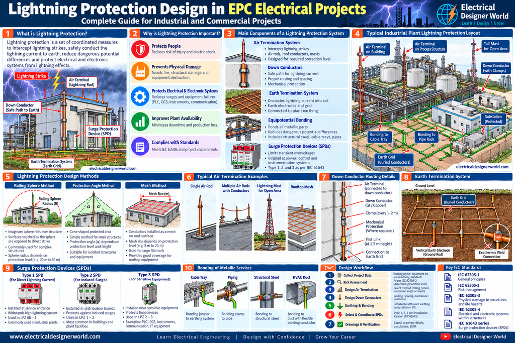
Table of Contents
Introduction
Lightning protection design is an important part of electrical engineering in industrial plants, commercial buildings, substations and infrastructure projects.
Lightning can cause physical damage to buildings, fires, electric shock hazards, equipment failures and interruptions to plant operations. It can also introduce transient overvoltages into power, instrumentation, control and communication circuits.
In an EPC project, electrical engineers must coordinate the external lightning protection system with the earthing network, electrical installation, structural design and internal surge protection.
Lightning protection is not just about installing a lightning rod on a roof. It requires a coordinated design that considers the risk to the structure, the lightning current path, bonding, separation distances and protection of electrical and electronic systems.
In this lesson, we will understand lightning protection design step by step using simple explanations and practical EPC examples.
Table of Contents
- What is lightning protection?
- Why is lightning protection important?
- Main components of a lightning protection system
- How lightning protection design is carried out
- Lightning protection methods
- Surge protection devices
- Practical EPC example
- Lightning protection drawings and deliverables
- Relevant IEC standards
- Common design mistakes
- Frequently asked questions
1. What Is Lightning Protection?
Lightning protection is a set of coordinated measures intended to reduce the risk of injury, physical damage and failures caused by lightning.
A lightning protection system (LPS) for a structure commonly includes an external system to intercept and conduct lightning current safely, together with bonding and other measures needed to reduce dangerous potential differences.
Protection of internal electrical and electronic systems may also require surge protection devices (SPDs), suitable cable routing, shielding, bonding and coordinated protective measures.
Simple lightning protection diagram
              LIGHTNING FLASH
                    |
                    v
           AIR TERMINAL / MAST
                    |
                    v
             DOWN CONDUCTOR
                    |
                    v
          EARTH TERMINATION SYSTEM
                    |
                    v
              EARTHING NETWORK

  Incoming power and signal circuits
                    |
                    v
        SURGE PROTECTION DEVICES
                    |
                    v
       ELECTRICAL / CONTROL EQUIPMENT
This is a conceptual diagram. The physical layout, conductor arrangement, bonding, separation distances and surge protection must follow the approved project design.
2. Why Is Lightning Protection Important in EPC Projects?
2.1 Protection against physical damage
A lightning strike can cause structural damage, fire and damage to roof-mounted equipment. A properly designed external protection system provides an intended interception and current-conduction path.
2.2 Protection of electrical equipment
Lightning can create transient overvoltages that damage transformers’ auxiliary systems, switchgear controls, PLCs, DCS equipment, instrumentation and communication interfaces.
The risk depends on the installation, exposure and surge path. External lightning protection alone does not guarantee that sensitive electronic equipment is protected.
2.3 Protection of people
Lightning protection and bonding measures help reduce specific risks associated with direct strikes, dangerous potential differences and lightning current flowing through a structure.
Safe working procedures during thunderstorms remain necessary; a lightning protection system does not make outdoor work automatically safe.
2.4 Improved plant availability
Damage to control systems, field instruments or power supplies can interrupt production even if the main electrical equipment remains operational.
A coordinated lightning protection and surge protection design can help reduce these risks.
3. Main Components of a Lightning Protection System
3.1 Air termination system
The air termination system is intended to intercept lightning strikes. Depending on the design, it may include air rods, roof conductors, masts or other approved arrangements.
Air terminals must be positioned according to the selected design method and required protection level. Installing one rod at an arbitrary location does not establish that an entire building or plant is protected.
3.2 Down conductors
Down conductors provide the intended path for lightning current from the air termination system to the earth termination system.
The design considers the required number and arrangement of conductors, current paths, mechanical protection, separation distances, routing and connections.
Down conductors should be coordinated with building façades, structural steel, cable routes, doors, access ways and underground services.
3.3 Earth termination system
The earth termination system disperses lightning current into the ground through the designed earthing arrangement.
It must be coordinated with the project’s earthing and bonding philosophy. The design should not assume that a separate lightning earth electrode can always be isolated from the plant earthing network; the appropriate arrangement depends on the applicable standard and project design.
3.4 Equipotential bonding
Bonding connects relevant conductive parts to help reduce dangerous potential differences during a lightning event.
Potential bonding interfaces may include:
- Structural steel
- Metallic pipework
- Cable trays and ladders
- Electrical enclosures
- Incoming metallic services
- The earthing network
- Surge protection interfaces
Bonding requirements depend on the installation and must be coordinated with separation-distance and insulation requirements.
3.5 Surge protection devices
Surge protection devices limit transient overvoltages and divert surge currents through suitable paths.
SPDs are selected and coordinated according to the circuit, system voltage, expected surge exposure, equipment withstand capability, prospective fault conditions and installation arrangement.
They may be required on power, instrumentation, control, data or communication circuits.
4. How Lightning Protection Design Is Carried Out in an EPC Project
A typical design workflow is:
Project data → Risk assessment → Protection level → Air termination design → Down conductor design → Earthing and bonding → SPD coordination → Drawings and verification
Step 1: Collect project information
Before beginning the design, review the available project documents.
Important inputs include:
- Plot plan and building layouts
- Building dimensions and heights
- Structural drawings
- Electrical Design Basis
- Equipment and instrument lists
- Single Line Diagrams (SLDs)
- Earthing design philosophy
- Cable routing and tray layouts
- Instrumentation and communication system details
- Hazardous-area classification, where applicable
- Client specifications and applicable standards
These documents help identify structures and equipment that may need lightning protection.
Step 2: Perform lightning risk assessment
The protection measures should be selected using the applicable risk assessment method.
Factors may include the structure’s dimensions, location, use, occupancy, construction, connected services and the consequences of damage.
The assessment determines whether protection is required and helps establish the appropriate protection measures.
For IEC-based projects, IEC 62305-2 addresses lightning risk management. The designer must use the applicable edition and project criteria rather than choosing a protection level based on building height alone.
Step 3: Determine the lightning protection class or level
Where required by the selected design method, the risk assessment and applicable standard establish the required lightning protection level or class.
This selection affects the design criteria for the air termination system, down conductors, separation distances and other components.
Do not assume that every industrial building automatically requires the same lightning protection class.
Step 4: Design the air termination system
The air termination system is arranged to provide the required coverage for the structure.
Common design methods include:
- Rolling sphere method
- Protection angle method
- Mesh method
The applicable method and its limitations depend on the structure, geometry and selected protection class.
Rolling sphere method
The rolling sphere method uses an imaginary sphere with a radius determined by the applicable lightning protection class. Surfaces that the sphere can touch are evaluated for exposure to a direct lightning strike under the method.
This approach is useful for evaluating complex industrial structures, rooftop equipment and masts.
Protection angle method
The protection angle method uses a geometric angle to define a protected region around an air termination element.
Its use is limited by the applicable standard, protection class and height or geometry conditions. It should not be applied universally to every structure.
Mesh method
The mesh method uses a network of conductors arranged over a roof or other suitable surface. The allowable mesh dimensions depend on the applicable protection class and standard.
The chosen method and the resulting coverage must be documented in the design.
Step 5: Design down conductors
The down conductor arrangement must provide suitable current paths from the air termination system to the earth termination system.
The engineer evaluates conductor routing, number and spacing of down conductors, connections, mechanical protection and separation from internal electrical systems.
Sharp bends, long detours and unnecessary loops should be avoided where the design standard restricts them, because they can affect the lightning current path and electrical stresses.
Structural steel may form part of a lightning protection arrangement only when it meets the applicable requirements and continuity and connection details are verified.
Step 6: Coordinate earthing and bonding
The lightning protection earth termination must be coordinated with the plant earthing network.
The design considers electrode arrangements, interconnection with other earthing systems, bonding to conductive services and interfaces with the external lightning protection system.
This step connects directly to Lesson 19: Earthing Design in EPC Electrical Projects.
A separate lightning earth electrode should not be assumed to be the correct solution for every installation. The arrangement must follow the selected standard, risk assessment and approved earthing philosophy.
Step 7: Select and coordinate SPDs
External lightning protection addresses direct-strike current paths, but lightning-induced surges can still enter through power and signal cables.
The designer must identify incoming services and vulnerable equipment, then determine where SPDs and other protective measures are needed.
Typical applications include:
- Main low-voltage distribution boards
- Sub-distribution boards
- PLC and DCS power supplies
- Instrumentation loops
- Communication and data lines
- Outdoor sensors and field instruments
SPD selection depends on system voltage, earthing arrangement, expected surge exposure, protection level, equipment withstand voltage and coordination with other SPDs.
The required SPD type and placement must be established by the applicable standard and design study. Do not select a device only by its nominal voltage.
5. Types of Lightning Protection Methods
| Method or measure | Purpose | Typical application |
|---|---|---|
| Air rods or masts | Intercept potential direct strikes | Buildings and exposed equipment |
| Roof conductor mesh | Provide distributed interception coverage | Suitable roof structures |
| Down conductors | Carry lightning current towards earth | Buildings and industrial structures |
| Earth termination system | Disperse current into the ground | Coordinated earthing network |
| Equipotential bonding | Reduce dangerous potential differences | Metallic services and structures |
| Surge protection devices | Limit transient overvoltages | Power and signal circuits |
These measures are complementary. The appropriate combination depends on the project risk assessment and design requirements.
6. Understanding Surge Protection Devices (SPDs)
An SPD is designed to limit transient overvoltages and divert surge currents. It is not a substitute for ordinary overcurrent protection, protective earthing or a complete lightning protection system.
Type 1 SPD
Type 1 SPDs are intended for applications where partial lightning currents may enter the installation. They are selected according to the applicable standard and installation exposure.
Type 2 SPD
Type 2 SPDs are commonly installed in distribution boards to protect against transient overvoltages, including induced lightning surges and switching surges.
Type 3 SPD
Type 3 SPDs may provide additional protection close to sensitive equipment, where the overall protection design requires them.
Important: The SPD arrangement must be coordinated. The protection level, connection length, earthing arrangement, upstream protection and manufacturer’s instructions all affect performance.
For signal and instrumentation circuits, suitable SPDs must match the circuit characteristics, including signal type, bandwidth and operating voltage.
7. Practical EPC Example: Lightning Protection for an Industrial Control Building
Consider an industrial plant with a control building containing PLC panels, network switches, instrumentation interfaces and low-voltage distribution boards.
A practical design workflow could include the following:
- Review the building dimensions, roof equipment and surrounding structures.
- Carry out the required lightning risk assessment.
- Establish the applicable protection class and design criteria.
- Design air terminals or roof conductors to provide the required coverage.
- Route down conductors or verify qualifying structural paths.
- Coordinate the earth termination system with the plant earthing network.
- Bond relevant conductive services according to the approved design.
- Evaluate incoming power, instrumentation and communication circuits for surge protection.
- Select and coordinate SPDs with the circuit and equipment requirements.
- Prepare the drawings, calculations, material schedule and inspection requirements.
For example, an outdoor pressure transmitter connected to a PLC may be exposed to surges entering through its field cable. The appropriate protection depends on the cable route, transmitter interface, signal characteristics, installation bonding and project risk assessment.
Installing a roof air terminal alone would not address every possible surge path into the control system.
8. Lightning Protection Drawings and EPC Deliverables
Depending on the project scope, the engineering team may prepare:
- Lightning protection design philosophy
- Lightning risk assessment
- Lightning protection layout
- Air terminal and roof conductor layout
- Down conductor routing and details
- Earth termination and bonding details
- Separation-distance calculations, where required
- SPD selection and coordination schedule
- SPD installation details
- Lightning protection material schedule
- Inspection, testing and maintenance requirements
These deliverables must be coordinated with civil, structural, electrical and instrumentation teams.
The designer should also identify interfaces with rooftop HVAC equipment, cable trays, metallic pipes, solar installations and other rooftop services where applicable.
9. Relevant IEC Standards for Lightning Protection
Use the applicable edition specified by the project. The IEC 62305 series was updated in 2024, and the IEC catalogue lists a 2026 series collection covering its four parts.
IEC 62305-1: General principles
Provides the general principles for protection of structures, installations, contents and people against lightning.
Official reference: https://webstore.iec.ch/en/publication/27136
IEC 62305-2: Risk management
Addresses assessment of lightning-related risk and selection of protection measures.
Official reference: https://webstore.iec.ch/en/publication/28137
IEC 62305-3: Physical damage to structures and life hazard
Addresses protection against physical damage using a lightning protection system and relevant measures to reduce injury risks. Confirm the applicable current edition through the IEC catalogue.
Official series reference: https://webstore.iec.ch/en/publication/6797
IEC 62305-4: Electrical and electronic systems within structures
Addresses measures to reduce permanent failures in electrical and electronic systems caused by lightning electromagnetic effects. Confirm the current edition and project requirements.
Official series reference: https://webstore.iec.ch/en/publication/6797
IEC 61643 series: Surge protection devices
IEC 61643 covers requirements and application principles for surge protection devices in relevant power and signal applications.
For low-voltage power systems, see IEC 61643-12:
https://webstore.iec.ch/en/publication/32531
Always check the applicable edition, amendments, national adoption and client engineering specifications before finalizing a design.
10. Common Lightning Protection Design Mistakes
- Installing an air rod without checking coverage: The entire structure and rooftop equipment must be evaluated using the selected design method.
- Ignoring risk assessment: The required protection measures should be based on an appropriate risk assessment and applicable criteria.
- Treating earthing as a separate afterthought: The lightning current path must be coordinated with the plant earthing and bonding philosophy.
- Ignoring down conductor routing: Conductor arrangement and separation from internal services can affect safety and performance.
- Assuming external protection prevents all surges: Internal power and signal circuits may still require SPDs.
- Selecting SPDs without coordination: Incorrect ratings, installation or coordination can reduce protection effectiveness.
- Ignoring instrumentation cables: Field signals and communication lines can provide paths for transient overvoltages.
- Failing to coordinate with civil and structural teams: Roof penetrations, foundations, structural steel and underground services must be considered.
- Skipping inspection and maintenance: Connections, conductors, SPDs and other components require inspection and maintenance as specified.
11. Frequently Asked Questions
What is lightning protection design in EPC electrical projects?
It is the process of assessing lightning risk and designing coordinated measures to protect structures, people and electrical or electronic systems against lightning effects.
What is the difference between lightning protection and earthing?
Lightning protection includes measures such as air terminals, down conductors, bonding and earth termination. Earthing is one part of that arrangement and also serves wider electrical safety functions.
Does every industrial building need a lightning rod?
Not necessarily. The required measures depend on the applicable risk assessment, standards, building characteristics and project specifications.
What is the rolling sphere method?
It is a design method that uses an imaginary sphere of a prescribed radius to evaluate which parts of a structure may be exposed to direct lightning strikes.
Can a lightning protection system prevent all equipment damage?
No. It reduces specific risks but cannot guarantee complete immunity. Surge protection, bonding, cable routing and equipment protection must also be considered.
What is the role of an SPD in lightning protection?
An SPD limits transient overvoltages and diverts surge currents through a suitable path, helping protect connected electrical or electronic equipment.
Which IEC standard is used for lightning protection design?
The IEC 62305 series is a principal reference for lightning protection of structures. The IEC 61643 series addresses relevant surge protection devices and their applications.
Conclusion
Lightning protection design is an important engineering activity in EPC electrical projects. It requires a coordinated approach covering risk assessment, air termination, down conductors, earth termination, bonding and surge protection.
An effective design protects more than the roof of a building. It considers how lightning current may enter or affect the installation, how dangerous potential differences can be reduced, and how electrical and electronic equipment can be protected against transient overvoltages.
For EPC electrical designers, understanding the relationship between lightning protection, earthing, cable routing and SPD coordination is essential for producing complete and reliable engineering deliverables.
Next lesson — Lesson 21: Electrical Cable Glanding, Termination and Cable Armour Earthing in EPC Projects.