
Earthing Design in EPC Electrical Projects – A Complete Guide
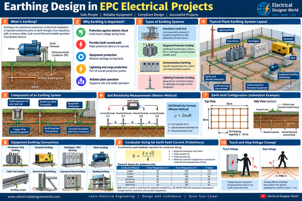
Table of Contents
Introduction
Earthing design is one of the most important activities in EPC electrical engineering. A properly designed earthing system helps protect people from electric shock, provides a path for fault current and supports the operation of electrical protection devices.
In an industrial plant, electrical equipment such as transformers, generators, motors, switchgear, distribution panels and cable trays must be connected to an appropriate earthing system according to the project specifications and applicable standards.
Imagine a fault inside an electric motor. If a live conductor touches the motor’s metallic body, the body can become electrically energized. Without suitable protective measures, a person touching the motor could receive an electric shock.
A correctly designed protective earthing system, combined with effective fault protection, helps reduce this risk.
In this lesson, we will understand earthing design step by step using simple explanations and practical EPC electrical engineering examples.
What Is Earthing in Electrical Engineering?
Earthing is the intentional connection of an electrical installation or designated conductive parts to earth through a designed earthing arrangement.
In protective earthing, exposed conductive parts of electrical equipment are connected to the protective earthing system so that dangerous touch voltages can be controlled and electrical faults can be cleared safely.
For example, the metallic body of a motor is connected to the protective earth conductor. If an insulation fault occurs, the fault-current path and protective device are intended to work together to disconnect the faulty circuit.
Simple earthing diagram
       415 V AC SUPPLY
              |
          MCC PANEL
              |
          POWER CABLE
              |
           ELECTRIC
             MOTOR
              |
       Metallic Motor Body
              |
       Protective Earth (PE)
              |
        PLANT EARTH GRID
              |
       EARTHING ELECTRODES
              |
             EARTH
The diagram illustrates the basic concept. In a real installation, the protective conductor is connected to the designated earthing terminal and plant earthing network in accordance with the approved design.
1. Why Is Earthing Design Important in EPC Projects?
Earthing design supports several important safety and operational functions.
1.1 Protection against electric shock
A fault can cause the metallic body of electrical equipment to become live. Protective earthing and automatic disconnection measures help limit the duration of dangerous conditions.
1.2 Fault-current path
The earthing and bonding system provides an intended path for fault current. The impedance of this path affects the fault current and the ability of protective devices to operate.
1.3 Equipment protection
An effective earthing and bonding arrangement helps reduce hazardous potential differences between conductive equipment parts.
1.4 Lightning and surge protection
Earthing forms part of a coordinated lightning protection and surge-protection system. Lightning protection requires its own design considerations, bonding arrangements and surge-current paths.
1.5 Reliable plant operation
Correct earthing and bonding help support electrical safety, reduce unwanted potential differences and provide suitable reference and bonding arrangements for instrumentation and control systems.
2. Important Earthing Terms Every Electrical Designer Must Know
Before starting an earthing design, understand these basic terms.
| Term | Simple explanation |
|---|---|
| Protective earthing | Connecting exposed conductive equipment parts to a protective earthing system |
| Earth electrode | A conductive element installed in soil or incorporated into a foundation to make an electrical connection with earth |
| Earth grid | An interconnected network of buried conductors, commonly used in substations and industrial plants |
| Earth conductor | A conductor used as part of the earthing arrangement |
| Protective conductor (PE) | A conductor used for protective earthing |
| Equipotential bonding | Connecting conductive parts to reduce potential differences between them |
| Soil resistivity | A property of soil that indicates how strongly it opposes the flow of electric current |
| Earth resistance | Resistance associated with an electrode or earthing arrangement under specified test conditions |
| Touch voltage | Voltage between conductive parts that a person can touch simultaneously |
| Step voltage | Voltage difference between two points on the ground separated by a person’s step |
Important: Earth resistance and soil resistivity are not the same. Soil resistivity is a property of the soil, while earth resistance relates to a particular electrode or earthing system and its installation conditions.
3. What Are the Main Types of Earthing Systems?
The earthing arrangement depends on the electrical system, voltage level, installation type and applicable standards.
3.1 Equipment protective earthing
Metallic enclosures, motor bodies, transformer tanks, switchgear structures and other exposed conductive parts are connected to the protective earthing system as required by the design.
3.2 Substation earth grid
An interconnected network of buried conductors is installed within or around a substation.
The grid helps manage earth potential rise and touch and step voltages during earth faults. Its design depends on fault current, fault duration, soil properties, grid geometry and other relevant parameters.
3.3 Earth electrodes
Earth electrodes may include rods, plates, strips, buried conductors or foundation electrodes, depending on the approved design and local requirements.
Electrodes are not selected only by their physical size. Their performance depends on soil conditions, electrode geometry, installation quality and interaction with other electrodes.
3.4 Instrumentation and control system earthing
Instrumentation systems may require specific protective bonding, functional earthing and cable-screen termination arrangements.
These must be coordinated with the instrumentation design, EMC requirements and equipment manufacturer’s recommendations. An isolated instrument earth must not be assumed to be the correct solution for every project.
4. How Earthing Design Is Carried Out in an EPC Project
A typical earthing design workflow includes the following activities.
Project requirements → Soil resistivity data → Fault-current study → Earthing philosophy → Grid and conductor design → Equipment connections → Safety verification → Drawings and testing
Step 1: Review project documents
The electrical designer reviews the relevant project documents before preparing the earthing layout.
Important inputs include:
- Electrical Design Basis
- Single Line Diagrams (SLDs)
- Electrical equipment list
- Short-circuit calculation and protection study
- Substation and equipment layout drawings
- Cable routing and cable tray layouts
- Civil and structural drawings
- Earthing and lightning protection specifications
- Applicable standards and local electrical regulations
The designer must identify the earthing requirements for each area, including substations, transformer yards, motor control centres, process areas and buildings.
Step 2: Obtain soil resistivity data
Soil resistivity is an important input for substation earth grid design.
Soil conditions can vary significantly across a plant. Moisture, soil composition, temperature and the presence of different soil layers can influence the measured values.
A soil resistivity survey is normally performed using an approved field method, such as the Wenner four-electrode method, where appropriate.
The results are used to develop a suitable soil model for the earth grid calculation.
Do not assume a standard soil resistivity value for every project. Use the site survey and the design basis.
Step 3: Determine the earth-fault current
The designer must identify the relevant earth-fault current that can flow into the earthing system.
The required input depends on the power system configuration, transformer neutral earthing, fault location, protection clearing time and current division between available return paths.
The total short-circuit current is not necessarily equal to the current injected into the earth grid.
For a substation earth grid, the design must account for the relevant grid current and fault duration according to the selected design method.
Step 4: Select the earthing philosophy
The earthing philosophy defines how electrical equipment and metallic structures are connected to the earthing system.
It typically identifies:
- Substation earth grid arrangements
- Equipment protective earthing connections
- Transformer neutral earthing
- Generator neutral earthing, where applicable
- Cable armour and metallic sheath bonding
- Cable tray and ladder bonding
- Building steel and structural bonding
- Lightning protection bonding
- Instrumentation and control system requirements
The philosophy must be coordinated across electrical, civil, structural, instrumentation and process disciplines.
Step 5: Design the earth grid and conductors
For substations and other installations requiring a designed earth grid, the engineer determines the grid configuration, conductor material and cross-sectional area, grid spacing, electrode arrangement and connection details.
The design must evaluate the expected thermal duty of conductors and joints, mechanical durability, corrosion conditions and electrical safety.
For a preliminary adiabatic thermal check, a commonly used form of the conductor-sizing equation is:
S = I × √t / k
Where:
- S = required conductor cross-sectional area in mm²
- I = relevant fault current in amperes
- t = fault duration in seconds
- k = material and temperature-dependent constant, consistent with the selected standard and units
This equation is a preliminary thermal-sizing relationship. The correct current, duration, conductor material, initial temperature, final temperature and applicable design criteria must be established before using it.
The final design must also consider mechanical strength, corrosion, connection performance and applicable minimum requirements.
Step 6: Connect equipment to the earthing system
The earthing layout identifies the required connections for electrical equipment and designated metallic structures.
Typical items include:
- Transformers and their tanks
- Generators and associated enclosures
- Switchgear and MCC panels
- Motors and local control stations
- Cable trays and ladders
- Junction boxes and electrical panels
- Buildings and structural steel
- Lightning protection components
Connections must use approved terminals, lugs, clamps, welded joints or other specified methods appropriate to the installation.
Cable trays and other metallic components should be bonded as required by the approved design. Their electrical continuity must not be assumed simply because sections are mechanically connected.
Step 7: Verify electrical safety
For a substation earth grid, a low measured earth resistance by itself does not establish that the system is safe.
The design must consider the applicable touch-voltage and step-voltage criteria, earth potential rise, fault duration, surface-layer properties and the expected distribution of current.
For low-voltage installations, protective conductor sizing, fault-loop impedance and automatic disconnection requirements must also be verified according to the applicable system and standards.
The checks required depend on the installation. Not every industrial earthing system requires the same calculation package.
5. Practical EPC Example: Earthing a Motor
Consider an industrial plant with a 415 V, three-phase motor supplied from an MCC.
The motor’s metallic body must be connected to the designated protective earthing system.
If a phase conductor comes into contact with the motor body due to insulation failure, a fault current may flow through the protective conductor and the available fault-return path.
The protective device must disconnect the faulty supply within the required time.
The designer must verify that:
- The motor protective earth connection is correctly specified.
- The protective conductor has adequate thermal and mechanical capacity.
- The fault-current path has suitable impedance for the protection arrangement.
- The selected protective device can disconnect the fault within the required time.
- Connections are properly installed and verified during inspection and testing.
The exact conductor size and protective-device requirements must be calculated for the actual installation. They cannot be determined from the motor voltage alone.
6. How Earthing Design Connects with Other EPC Electrical Activities
Earthing is not an isolated drawing. It is connected to several other electrical engineering deliverables.
| EPC activity | Relationship to earthing |
|---|---|
| Load list | Identifies the electrical equipment requiring protective connections |
| Single Line Diagram | Shows the power system and relevant neutral earthing arrangements |
| Transformer sizing and specification | Provides transformer and neutral-system information |
| Short-circuit calculation | Provides fault-current information for design checks |
| Protection and coordination | Establishes protection operation and relevant fault-clearing times |
| Cable schedule | Identifies cables, including required protective conductors where applicable |
| Cable tray routing | Supports coordination of bonding and earthing connections |
| Equipment layout | Defines equipment locations and earthing connection requirements |
| Civil and structural design | Coordinates buried conductors, foundations, steelwork and underground services |
This is why an EPC electrical designer must understand the relationship between the SLD, short-circuit study, protection study, equipment layout and earthing drawings.
7. Important Earthing Design Standards
The applicable standards depend on the project location, voltage level, installation type, client specification and governing regulations.
Useful references include:
IEC 60364-5-54 – Earthing arrangements and protective conductors
This IEC standard addresses earthing arrangements, protective conductors and protective bonding conductors for electrical installations.
Official reference: https://webstore.iec.ch/en/publication/68865
IEEE Std 80 – Guide for Safety in AC Substation Grounding
IEEE Std 80-2013 provides guidance for safe grounding practices in AC substations, including the evaluation of touch and step voltages. Confirm the applicable edition and current project requirements before specifying it.
Official IEEE reference: https://standards.ieee.org/ieee/80/4089/
The designer should also review the applicable local electrical regulations, client engineering standards and project-specific design basis. Referencing a standard does not replace carrying out the required design calculations.
8. Common Earthing Design Mistakes
Avoid these mistakes when preparing EPC earthing deliverables.
- Assuming a fixed earth resistance target: Acceptance criteria must follow the applicable design basis and safety requirements.
- Ignoring soil resistivity: Substation grid design requires appropriate soil data.
- Using total fault current without checking grid current: The current entering the earth grid may differ from the total fault current.
- Selecting conductors based only on current rating: Fault duration, temperature limits, mechanical strength and corrosion must also be considered.
- Ignoring touch and step voltages: Earth resistance alone is not a complete measure of substation safety.
- Leaving cable trays or structures unbonded: Electrical continuity and bonding requirements must be explicitly addressed.
- Ignoring coordination with civil works: Buried conductors can conflict with foundations, drainage, underground utilities and other services.
- Treating lightning protection and protective earthing as unrelated systems: Their interfaces and bonding arrangements must be coordinated.
- Failing to verify installation quality: Inspection, continuity checks and required commissioning tests are part of the completed installation.
9. Earthing Design Deliverables in an EPC Project
Depending on the project scope, the electrical engineering team may prepare the following deliverables:
- Earthing design philosophy
- Soil resistivity report or survey data
- Earthing calculation report
- Substation earth grid calculation
- Earthing layout drawings
- Equipment earthing connection details
- Earthing conductor and material schedule
- Earthing grid sections and installation details
- Bonding details for cable trays and structural steel
- Interface details for lightning protection
- Inspection and testing requirements
These documents help the engineering, procurement, construction and commissioning teams implement the approved earthing system consistently.
10. Frequently Asked Questions
What is earthing design in EPC electrical projects?
Earthing design is the engineering process of specifying and verifying the protective earthing, bonding and, where required, earth grid arrangements for an electrical installation.
What is the difference between earthing and grounding?
In electrical engineering, earthing and grounding are often used for similar concepts. Usage varies by region and standard. The precise meaning depends on whether the discussion concerns protective earthing, system neutral grounding or functional earthing.
Is a low earth resistance always safe?
No. A low resistance measurement alone does not prove that a system meets all safety requirements. Relevant touch and step voltages, fault current, fault duration, protective-device operation and the installation type must be considered.
Why is soil resistivity required for earth grid design?
Soil resistivity helps the engineer model how current disperses into the ground. It is an important input for calculating earth grid performance and evaluating safety criteria.
How is an earthing conductor sized?
The conductor is selected by considering fault-current thermal duty, fault duration, material properties, mechanical strength, corrosion and applicable standards. A project-specific calculation is required.
Which standard is used for earthing design?
IEC 60364-5-54 is relevant to earthing arrangements and protective conductors in low-voltage installations. IEEE Std 80 is a key reference for AC substation grounding safety. The applicable project standards must be confirmed for each installation.
Conclusion
Earthing design is a fundamental part of EPC electrical engineering because it supports personnel safety, equipment protection and reliable fault clearance.
An electrical designer must understand soil resistivity, earth-fault current, protective conductors, earth grids, equipment bonding and the applicable safety criteria. These elements must be coordinated with short-circuit calculations, protection and coordination studies, cable schedules, equipment layouts and civil engineering drawings.
A successful earthing design is not simply a drawing showing earth conductors. It is a coordinated engineering solution supported by calculations, appropriate standards, installation details and verification.
In the next lesson, Lesson 20, we will learn about Lightning Protection Design in EPC Electrical Projects.