
How Generator, ATS and UPS Are Shown in an SLD
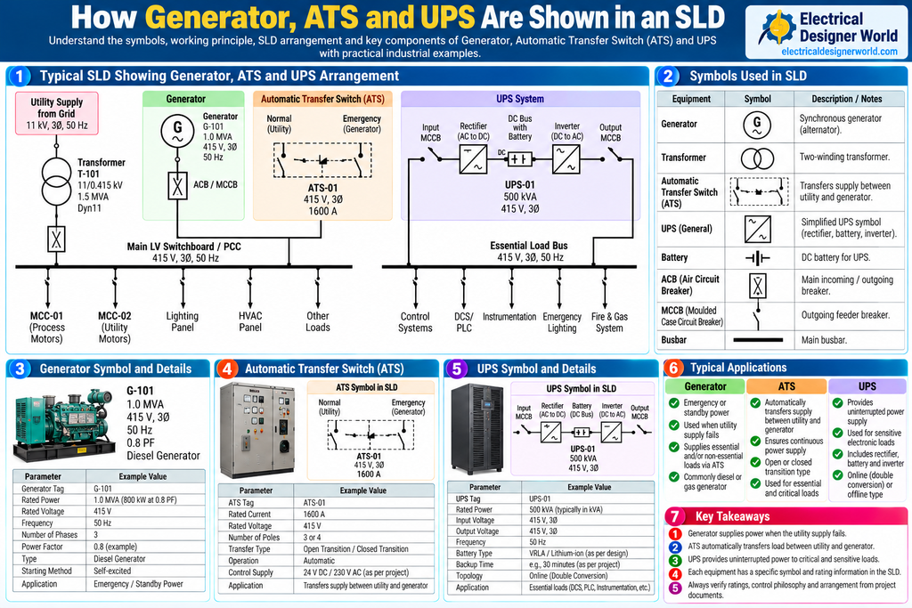
Table of Contents
Understanding how generators, ATS and UPS are shown in an SLD is important for electrical engineers and designers working on industrial Engineering, Procurement, and Construction (EPC) projects. These systems help maintain electrical power when the normal utility supply fails, but each performs a different function.
A generator provides an alternative electrical power source, an Automatic Transfer Switch (ATS) transfers the load between available sources, and an Uninterruptible Power Supply (UPS) maintains power to critical loads during supply interruptions.
In an industrial electrical Single Line Diagram (SLD), these systems are represented by equipment symbols, switching arrangements, electrical connections, and equipment ratings.
This guide explains how to identify generator, ATS, and UPS symbols in an SLD, trace the power flow, understand their functions, and verify the associated electrical design information.
For more practical electrical design tutorials, visit Electrical Designer World.
What Is a Generator in an Electrical SLD?
An electrical generator is a machine that converts mechanical energy into electrical energy. In industrial facilities, a standby generator commonly supplies backup power when the normal utility supply becomes unavailable.
In an SLD, a generator may be represented by a circle containing the letter G or another symbol specified by the drawing standard.
The drawing may show the generator tag, rated power, voltage, frequency, number of phases, and connection to the associated switchgear.
For example:
G-101 | 1000 kVA | 415 V | Three-phase | 50 Hz
These values are illustrative. Actual generator ratings must be verified against the approved generator datasheet and project specifications.
Main functions of a generator
- Provide standby or emergency power.
- Supply designated loads during utility failure.
- Support essential plant operations where backup power is required.
- Supply an emergency bus or switchboard through the specified switching arrangement.
- Support automatic or manual operation according to the control philosophy.
Information to identify on a generator SLD
Check the generator tag, rated kW or kVA, voltage, frequency, phase arrangement, circuit breaker, and connection to the emergency distribution system.
Also verify whether the generator is intended to supply the entire plant or only selected essential loads.
What Is an ATS in an Electrical SLD?
An Automatic Transfer Switch (ATS) transfers a load between two power sources according to its control logic and operating conditions.
A common arrangement uses the utility supply as the normal source and a standby generator as the alternative source.
When the normal source fails and the generator becomes available, the ATS transfers the designated load to the generator according to the specified transfer sequence. When the normal supply is restored, the system may transfer the load back according to its configured control logic.
An ATS does not generate electricity and does not provide the energy storage function of a UPS.
Main functions of an ATS
- Monitor the availability of the normal and alternative sources.
- Initiate or coordinate transfer between sources.
- Prevent unintended connection of incompatible sources where required by the switching arrangement.
- Support automatic or manual transfer operation.
- Supply designated loads from the available source.
The transfer mechanism may use contactors, circuit breakers, or a dedicated transfer-switch assembly. Its operating sequence depends on the approved design.
Information to identify on an ATS SLD
Look for:
- ATS equipment tag.
- Normal and alternative source connections.
- Rated voltage and current.
- Number of poles.
- Open-transition or closed-transition arrangement, where applicable.
- Control and interlocking references.
- Downstream load or bus identification.
Important: Closed-transition transfer requires appropriate synchronization and source-paralleling provisions. Do not assume that an ordinary ATS permits parallel operation of the utility and generator.
What Is a UPS in an Electrical SLD?
A Uninterruptible Power Supply (UPS) provides conditioned electrical power to designated loads when the normal input supply is interrupted or becomes unsuitable.
A typical UPS system includes a rectifier or charger, a battery system, an inverter, and switching or bypass arrangements. The exact configuration depends on the UPS topology.
The battery provides stored energy during a supply interruption, allowing critical loads to continue operating within the UPS capacity and available battery autonomy.
Main functions of a UPS
- Maintain power to critical loads during supply interruptions.
- Provide power conditioning according to the UPS design.
- Support control systems and sensitive electronic equipment.
- Provide battery-backed operation for a specified duration.
- Transfer to a bypass path under defined operating conditions where the design includes one.
Typical UPS loads include Distributed Control Systems (DCS), Programmable Logic Controllers (PLC), instrumentation, communication equipment, and selected emergency control systems.
A UPS is not necessarily intended to supply all plant loads. Its output capacity and battery autonomy must match the specified critical-load requirements.
Information to identify on a UPS SLD
Check the UPS tag, rated kVA or kW, input and output voltage, battery arrangement, autonomy, bypass arrangement, and connected essential loads.
For technical background on electrical installations and power distribution, consult Schneider Electric’s Electrical Installation Guide.
How Generator, ATS and UPS Work Together
A generator, ATS, and UPS may be used together in an industrial electrical system because they perform complementary functions.
Consider a facility with a utility supply, a standby generator, and a UPS supplying critical control equipment.
- Under normal conditions, the utility supply provides electrical power.
- If the utility fails, the UPS battery temporarily maintains power to its connected critical loads.
- The generator starts according to the standby control sequence.
- Once the generator voltage and frequency are acceptable, the ATS transfers its designated loads to the generator.
- The UPS continues supplying its critical loads from the available input and recharges its battery as appropriate.
- When utility power is restored, the transfer system returns to normal supply according to its control philosophy.
The UPS bridges the interruption for its connected loads; the generator provides longer-duration backup subject to fuel, rating, and operating constraints; and the ATS switches designated loads between sources.
The exact sequence depends on the control design, UPS topology, and transfer-switch arrangement.
Typical SLD Showing Generator, ATS and UPS
The following simplified diagram illustrates one possible arrangement. The ATS supplies a designated essential distribution bus, while a UPS supplies selected critical loads.
              UTILITY SUPPLY
                    |
             MAIN SWITCHBOARD
                    |
          +---------+----------+
          |                    |
       NORMAL              NORMAL INPUT
       SOURCE               TO ATS
                               |
GENERATOR G-101                |
       |                       |
 GENERATOR CB                  |
       |                       |
       +------> ALTERNATIVE ---+
                    SOURCE
                       |
                      ATS
                       |
              ESSENTIAL LOAD BUS
                       |
             +---------+---------+
             |                   |
          ESSENTIAL           UPS INPUT
           LOADS                  |
                               RECTIFIER
                                  |
                               DC BATTERY
                                  |
                               INVERTER
                                  |
                              UPS OUTPUT
                                  |
                             CRITICAL LOADS
This is a conceptual example, not a construction-approved SLD. A real design may use separate switchboards, dedicated UPS distribution boards, maintenance bypasses, static bypasses, or different source arrangements.
The UPS may be supplied from the utility bus, generator-backed bus, or another designated source depending on the project’s reliability requirements.
How to Read Generator, ATS and UPS Symbols Step by Step
Step 1: Identify the normal utility supply
Locate the incoming utility source and identify the main switchboard or distribution bus.
Record the voltage, source tag, and relevant switching equipment shown on the SLD.
Step 2: Locate the generator symbol
Find the generator tag and trace its output through the generator circuit breaker to the intended distribution point.
Check the generator rating, output voltage, frequency, and the bus or transfer-switch connection.
Step 3: Identify the ATS and its two sources
Follow both incoming paths to the ATS.
Determine which input is the normal source and which is the alternative source. Verify the rated voltage, current, poles, and transfer arrangement.
Step 4: Trace the ATS output
Follow the outgoing connection from the ATS to the essential load bus or designated switchboard.
Identify which loads receive power from this bus and confirm whether the generator is intended to support all of them.
Step 5: Locate the UPS
Find the UPS symbol and trace its input and output connections.
Identify the rectifier or charger, battery, inverter, and any bypass arrangements shown.
Step 6: Identify critical loads
Check which loads are connected to the UPS output. These may include control systems, instrumentation, communication equipment, or other loads designated by the project.
Step 7: Verify the associated documents
Cross-check generator, ATS, and UPS information against the equipment datasheets, load list, emergency power philosophy, UPS autonomy calculation, and relevant control schematics.
Common Symbols Used for Generator, ATS and UPS in an SLD
Electrical symbols can differ depending on the applicable standard, software library, and project drawing convention. Always check the SLD legend before interpreting an unfamiliar symbol.
| Equipment | Common representation | What to check |
|---|---|---|
| Generator | Circle with G or generator symbol | Tag, kW/kVA, voltage, frequency |
| Transformer | Two overlapping circles or specified transformer symbol | Voltage ratio, rating, vector group |
| ATS | Transfer-switch symbol or labeled switching assembly | Normal source, alternative source, output |
| Circuit breaker | Standard breaker symbol | Rating, poles, protection |
| Battery | Battery symbol or labeled battery block | DC voltage, capacity, autonomy |
| UPS | UPS block or rectifier-battery-inverter representation | Rating, input, output, bypass |
| Busbar | Heavy line | Voltage, bus rating, load connections |
For standardized graphical symbols, consult the International Electrotechnical Commission (IEC). The applicable project legend and approved drawings take precedence when interpreting project-specific symbols.
Important Ratings to Check in the SLD
Generator ratings
Verify the generator’s rated power, output voltage, frequency, phase arrangement, power factor where specified, and short-circuit or protection information relevant to the design.
Generator sizing must consider the expected load, motor starting, transient performance, load steps, and operating requirements.
ATS ratings
Check the rated operational voltage and current, number of poles, source arrangement, transfer type, and short-circuit withstand or conditional rating as specified.
The ATS and associated protection must be suitable for the system’s prospective fault current and installation requirements.
UPS ratings
Check the rated kVA and kW, input and output voltage, battery voltage, autonomy, bypass arrangement, and expected load profile.
The battery autonomy must be calculated using the specified load, battery characteristics, operating conditions, and design requirements.
Common Mistakes When Reading Generator, ATS and UPS in an SLD
1. Assuming the generator starts instantly
A standby generator requires starting and stabilization time. The UPS must be designed to support its connected loads for the required interval until an acceptable alternative supply is available.
2. Assuming an ATS stores energy
An ATS switches sources; it does not provide battery backup. Energy storage is provided by the UPS battery or another designed storage system.
3. Assuming the UPS supplies the entire plant
A UPS usually supplies selected critical loads. Confirm the UPS load schedule and rated capacity.
4. Ignoring the generator’s load capability
The generator must support the intended operating load, starting requirements, and transient performance. Its rating cannot be selected from total kW alone without considering the relevant design factors.
5. Overlooking ATS interlocking and transfer type
Verify the transfer arrangement, source compatibility, and any synchronization requirements. Never assume that both sources can be connected in parallel.
6. Ignoring the UPS bypass path
The bypass path may affect the load supply during maintenance, overload, or UPS failure. Check the actual UPS topology and operating philosophy.
7. Confusing emergency loads with UPS loads
Some emergency loads are generator-backed but not UPS-backed. Other critical loads may require UPS supply. Follow the project load classification and emergency power philosophy.
Generator, ATS and UPS SLD Review Checklist
Use this checklist when reviewing an industrial emergency power SLD.
- Normal utility supply is identified.
- Generator tag and ratings are available.
- Generator circuit breaker and output connection are traceable.
- ATS normal and alternative sources are identified.
- ATS rating and transfer arrangement are verified.
- Essential load bus and connected loads are identified.
- UPS input and output paths are traceable.
- Battery arrangement and required autonomy are verified.
- Critical loads are identified.
- Generator starting and transfer sequences are coordinated.
- Equipment ratings agree with approved datasheets.
- Latest approved SLD and control documents are used.
Frequently Asked Questions (FAQs)
1. How is a generator shown in an electrical SLD?
A generator is commonly represented by a circle containing G or another specified generator symbol. The SLD may show its tag, rated power, voltage, frequency, and connection to a circuit breaker or switchboard.
2. What does ATS mean in an electrical SLD?
ATS means Automatic Transfer Switch. It transfers designated loads between a normal source and an alternative source according to its control logic and the specified switching arrangement.
3. How is a UPS shown in an SLD?
A UPS may be shown as a labeled equipment block or as a simplified rectifier, battery, and inverter arrangement. The project drawing may also show input, output, and bypass connections.
4. What is the difference between a generator and a UPS?
A generator produces electrical power from mechanical energy and can supply loads for an extended period while operating within its limits. A UPS provides uninterrupted power to its connected loads using stored energy and its power-conversion system during supply interruptions.
5. Why are both an ATS and a UPS used?
The ATS transfers designated loads between available power sources, while the UPS bridges supply interruptions for its connected critical loads. Together, they can improve continuity of supply when designed for the intended load and operating sequence.
6. Does an ATS always connect the utility and generator?
No. An ATS can transfer between different specified sources. A common arrangement uses utility power and a standby generator, but the actual configuration depends on the project design.
7. Which documents should I check after reading this part of the SLD?
Check the generator datasheet, ATS datasheet, UPS datasheet, essential-load list, UPS autonomy calculation, emergency power philosophy, control schematics, and approved electrical SLD.
Conclusion
Understanding how generator, ATS and UPS are shown in an SLD helps electrical designers trace normal and backup power supplies, identify source-transfer arrangements, and understand how critical loads are maintained during a utility failure.
The generator supplies alternative power, the ATS transfers designated loads between sources, and the UPS bridges supply interruptions for its connected critical loads.
Always verify the symbols, ratings, transfer sequence, battery autonomy, and equipment connections against the approved SLD, datasheets, and project control philosophy before using the information for electrical design.
For more practical electrical engineering tutorials, visit Electrical Designer World.