
Day 6: Kirchhoff’s Laws – KCL and KVL with Solved Examples
Welcome to Day 6 of the Electrical Fundamentals – Zero to Advanced course at Electrical Designer World!
In the previous lessons, we learned about voltage, current, resistance, Ohm’s law, series circuits, parallel circuits, and electrical power. Today, we will study two important rules used to analyse electrical circuits: Kirchhoff’s Current Law (KCL) and Kirchhoff’s Voltage Law (KVL).
Ohm’s law is useful for calculating voltage, current, and resistance in individual components. However, when a circuit contains multiple branches and several voltage sources, we often need additional equations to find the unknown currents and voltages.
This is where Kirchhoff’s laws become useful.
In this lesson, you will learn the meaning of KCL and KVL, their formulas, sign conventions, circuit diagrams, worked numerical examples, and practical applications in electrical engineering.
Table of Contents
1. What Are Kirchhoff’s Laws?
Kirchhoff’s laws are fundamental rules used to analyse electrical circuits. They are based on two conservation principles:
- Conservation of electric charge.
- Conservation of energy.
There are two main laws.
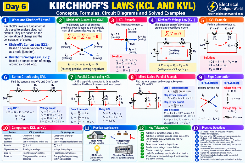
Kirchhoff’s Current Law (KCL): The algebraic sum of currents at a circuit node is zero.
Kirchhoff’s Voltage Law (KVL): The algebraic sum of voltages around a closed circuit loop is zero.
These laws help engineers determine unknown currents, voltage drops, and component voltages in electrical networks.
They are commonly used together with Ohm’s law to solve circuits containing multiple resistors, branches, and sources.
2. Kirchhoff’s Current Law (KCL)
Kirchhoff’s Current Law states that the total current entering a node equals the total current leaving that node.
A node is a point or electrically continuous region where two or more circuit elements connect.
The principle follows from conservation of electric charge: charge does not continuously accumulate at an ideal circuit node.
KCL formula
Sum of currents entering a node = Sum of currents leaving a node.
Alternatively, using an algebraic sign convention:
ΣI = 0
Example
Suppose a node has two currents entering it:
- I₁ = 5 A
- I₂ = 3 A
Two currents leave the node:
- I₃ = 4 A
- I₄ = Unknown
Using KCL:
I₁ + I₂ = I₃ + I₄
5 + 3 = 4 + I₄
8 = 4 + I₄
I₄ = 4 A
Therefore, the unknown current leaving the node is 4 A.
Why is KCL important?
KCL is useful when analysing parallel circuits, current-divider circuits, electrical distribution networks, and complex circuits containing several branches.
Whenever multiple current paths meet at a node, KCL helps determine the unknown branch currents.
3. KCL Formula and Sign Convention
There are two common ways to apply KCL.
Method 1: Entering current equals leaving current
Write all entering currents on one side and all leaving currents on the other side.
For example:
I₁ + I₂ = I₃ + I₄
This method is straightforward for beginners.
Method 2: Algebraic sum of currents equals zero
Choose a sign convention, such as:
- Entering currents: positive.
- Leaving currents: negative.
Then:
I₁ + I₂ − I₃ − I₄ = 0
Both methods produce the same answer when used consistently.
Important: The assumed current directions do not have to be correct initially. If a calculated current is negative, its actual direction is opposite to the direction you assumed.
4. Solved KCL Examples
Example 1: Find the missing current
At a node, 10 A enters and two currents of 4 A and I₃ leave. Find I₃.
Given:
Entering current = 10 A
Leaving currents = 4 A and I₃
Using KCL:
10 = 4 + I₃
I₃ = 10 − 4
Answer: I₃ = 6 A
Example 2: Multiple currents entering a node
Three currents enter a node: 2 A, 3 A, and 5 A. Two currents leave the node: 4 A and I₅. Calculate I₅.
Using KCL:
2 + 3 + 5 = 4 + I₅
10 = 4 + I₅
Answer: I₅ = 6 A
Example 3: Calculate total current in a parallel circuit
A 12 V supply is connected across three parallel resistors:
- R₁ = 6 Ω
- R₂ = 12 Ω
- R₃ = 24 Ω
Calculate the total current.
First, calculate each branch current using Ohm’s law.
For R₁:
I₁ = 12 / 6 = 2 A
For R₂:
I₂ = 12 / 12 = 1 A
For R₃:
I₃ = 12 / 24 = 0.5 A
Using KCL:
Iₜ = I₁ + I₂ + I₃
Iₜ = 2 + 1 + 0.5
Answer: Total current = 3.5 A
This example shows how Ohm’s law and KCL work together.
5. Kirchhoff’s Voltage Law (KVL)
Kirchhoff’s Voltage Law states that the algebraic sum of all voltage rises and voltage drops around any closed circuit loop is zero.
A closed loop is a complete path through a circuit that starts and ends at the same point.
KVL follows from conservation of energy. When charge completes a circuit loop, the total energy gained from voltage sources equals the total energy lost across circuit components.
KVL formula
ΣV = 0
In simple terms:
Total voltage rises = Total voltage drops.
Example
A circuit contains a 12 V battery and two series resistors with voltage drops of 5 V and V₃.
Using KVL:
12 − 5 − V₃ = 0
7 − V₃ = 0
V₃ = 7 V
The voltage drops add up to the supply voltage:
5 + 7 = 12 V
Therefore, the circuit satisfies KVL.
6. KVL Formula and Sign Convention
To apply KVL correctly, choose a direction to travel around the loop. You can travel clockwise or anticlockwise, but use the same direction consistently within the equation.
For the passive sign convention commonly used with resistors:
- Crossing a resistor in the direction of current gives a voltage drop of IR.
- Crossing a resistor opposite to the current direction gives a voltage rise of IR.
- Crossing an ideal source from its negative terminal to its positive terminal gives a voltage rise.
- Crossing an ideal source from its positive terminal to its negative terminal gives a voltage drop.
A practical method
- Choose a direction around the loop.
- Mark voltage polarities across the components.
- Identify voltage rises and voltage drops.
- Write the algebraic sum of voltages.
- Set the sum equal to zero.
- Solve the equation and check the result.
Different sign conventions are possible. The key is to apply the selected convention consistently.
7. Solved KVL Examples
Example 1: Find an unknown voltage
A 24 V source supplies a series circuit containing two resistors. The first resistor has a voltage drop of 6 V, and the second has a voltage drop of V₃.
Using KVL:
24 − 6 − V₃ = 0
18 − V₃ = 0
Answer: V₃ = 18 V
Example 2: Find current using KVL and Ohm’s law
A 30 V DC source is connected to three series resistors:
- R₁ = 5 Ω
- R₂ = 10 Ω
- R₃ = 15 Ω
Calculate the circuit current.
The total resistance is:
Rₜ = 5 + 10 + 15
Rₜ = 30 Ω
Using Ohm’s law:
I = V / Rₜ
I = 30 / 30
Answer: I = 1 A
Now calculate the voltage drops:
V₁ = 1 × 5 = 5 V
V₂ = 1 × 10 = 10 V
V₃ = 1 × 15 = 15 V
Check KVL:
30 − 5 − 10 − 15 = 0
The result satisfies KVL.
Example 3: Find the current in a two-resistor loop
A 24 V source is connected to two series resistors of 4 Ω and 8 Ω.
Using KVL:
24 − 4I − 8I = 0
24 − 12I = 0
12I = 24
Answer: I = 2 A
Voltage across the first resistor:
V₁ = 2 × 4 = 8 V
Voltage across the second resistor:
V₂ = 2 × 8 = 16 V
Verification:
8 + 16 = 24 V
The voltage drops equal the source voltage.
8. Applying KCL and KVL to Electrical Circuits
In practical circuit analysis, engineers often need both laws.
Consider a circuit with a voltage source, a series resistor, and two parallel resistors.
First, use the parallel-resistance formula and Ohm’s law to determine the total circuit current.
Next, use KVL to calculate the voltage drop across the series resistor and the voltage across the parallel section.
Finally, use Ohm’s law to calculate the individual branch currents and KCL to verify that the sum of the branch currents equals the total current.
This systematic approach helps analyse circuits containing multiple branches and components.
Worked mixed-circuit example
A 24 V source is connected to a 4 Ω resistor in series with two parallel resistors of 6 Ω and 12 Ω.
Step 1: Calculate the parallel resistance
Rₚ = (6 × 12) / (6 + 12)
Rₚ = 72 / 18
Rₚ = 4 Ω
Step 2: Calculate total resistance
Rₜ = 4 + 4
Rₜ = 8 Ω
Step 3: Calculate total current
Iₜ = 24 / 8
Iₜ = 3 A
Step 4: Calculate the voltage drop across the series resistor
V₁ = 3 × 4
V₁ = 12 V
Step 5: Calculate the voltage across the parallel section
Vₚ = 24 − 12
Vₚ = 12 V
Step 6: Calculate branch currents
I₁ = 12 / 6 = 2 A
I₂ = 12 / 12 = 1 A
Step 7: Verify KCL
Iₜ = I₁ + I₂
3 = 2 + 1
The current balance is correct.
Step 8: Verify KVL
24 − 12 − 12 = 0
The voltage balance is also correct.
This example demonstrates how KCL, KVL, and Ohm’s law work together to analyse a mixed circuit.
9. Difference Between KCL and KVL
| Property | KCL | KVL |
|---|---|---|
| Full name | Kirchhoff’s Current Law | Kirchhoff’s Voltage Law |
| Main principle | Conservation of electric charge | Conservation of energy |
| Applied to | A circuit node | A closed circuit loop |
| Formula | ΣI = 0 | ΣV = 0 |
| Determines | Unknown currents | Unknown voltages |
| Typical application | Parallel branches and current balance | Series paths and loop voltage balance |
KCL and KVL are complementary rules. Using them together with Ohm’s law provides a foundation for solving a wide range of electrical circuit problems.
10. Practical Applications of Kirchhoff’s Laws
Electrical circuit analysis
KCL and KVL help calculate unknown currents and voltages in networks containing resistors, sources, and multiple branches.
Electronic circuits
Engineers use Kirchhoff’s laws to analyse circuits containing components such as resistors, capacitors, inductors, and semiconductor devices, alongside the appropriate component equations.
Electrical troubleshooting
Measured voltages and currents can be checked against expected circuit values. Differences may indicate wiring issues, incorrect component values, faulty connections, or other problems requiring investigation.
Electrical engineering design
Understanding KCL and KVL supports more advanced calculations involving electrical networks, voltage drops, load distribution, and circuit behaviour.
In EPC electrical design, these laws strengthen the fundamentals needed to understand electrical calculations and power distribution systems.
Frequently Asked Questions
1. What is Kirchhoff’s Current Law?
KCL states that the algebraic sum of currents entering and leaving a node is zero. The total current entering a node equals the total current leaving it.
2. What is Kirchhoff’s Voltage Law?
KVL states that the algebraic sum of voltage rises and voltage drops around a closed loop is zero.
3. What is the difference between KCL and KVL?
KCL is applied at circuit nodes to analyse current balance. KVL is applied around closed loops to analyse voltage balance.
4. Why is KCL based on conservation of charge?
Electric charge cannot continuously accumulate at an ideal circuit node in the standard lumped-circuit model. Therefore, the current entering the node must balance the current leaving it.
5. Why is KVL based on conservation of energy?
When a charge completes a circuit loop, its net energy change around the loop is zero under the usual lumped-circuit assumptions. Voltage rises and drops therefore balance.
6. Can KCL and KVL be used with Ohm’s law?
Yes. Ohm’s law provides component relationships between voltage, current, and resistance, while KCL and KVL provide equations for the network.
7. Can Kirchhoff’s laws be used in AC circuits?
Yes. They can be applied to AC circuits, including using phasor quantities for sinusoidal steady-state analysis. Appropriate component models and sign conventions are required.
8. What is the next lesson in this course?
Day 7 covers basic circuit analysis, combining Ohm’s law, series and parallel circuits, KCL, and KVL to solve complete circuit problems.
Day 6 Practice Questions
Test your understanding of Kirchhoff’s laws.
- At a node, 8 A enters and 3 A leaves. Calculate the remaining current leaving the node.
- Three currents enter a node: 2 A, 4 A, and 6 A. Two currents leave: 5 A and I₃. Find I₃.
- A 12 V source has voltage drops of 4 V and V₂ around a loop. Find V₂.
- A 24 V source is connected to two series resistors of 4 Ω and 8 Ω. Calculate the current using KVL.
- State the formula for Kirchhoff’s Current Law.
- State the formula for Kirchhoff’s Voltage Law.
- Which law is applied at a node?
- Which law is applied around a closed loop?
- A 24 V source supplies a 4 Ω series resistor followed by 6 Ω and 12 Ω parallel resistors. Calculate total current.
- Explain the sign convention used when crossing a resistor in the direction of current.
Answer Key
- 8 − 3 = 5 A.
- 2 + 4 + 6 = 5 + I₃, so I₃ = 7 A.
- 12 − 4 − V₂ = 0, so V₂ = 8 V.
- Total resistance = 12 Ω; current = 24 / 12 = 2 A.
- ΣI = 0.
- ΣV = 0.
- Kirchhoff’s Current Law.
- Kirchhoff’s Voltage Law.
- Parallel resistance = 4 Ω; total resistance = 8 Ω; total current = 3 A.
- Under the passive sign convention, crossing a resistor in the direction of current is a voltage drop of IR.
Further Reading: Kirchhoff’s Laws
Explore these educational resources to strengthen your understanding of circuit analysis:
- All About Circuits – Textbook and Learning Resources — explore circuit theory, current, voltage, and network analysis.
- OpenStax College Physics 2e — review electrical current, resistance, and Ohm’s law.
- Schneider Electric Electrical Installation Guide — explore practical electrical installation and distribution concepts.
Conclusion
Kirchhoff’s laws are essential tools for understanding and analysing electrical circuits.
Remember the two key rules:
- KCL: The total current entering a node equals the total current leaving it.
- KVL: The total voltage rises and drops around a closed loop balance.
When combined with Ohm’s law, these rules help you solve circuits involving multiple resistors, current branches, voltage sources, and mixed series-parallel arrangements.
Practise the examples until you can identify nodes and loops, establish equations, apply sign conventions, and verify your answers.
Continue learning:
- Explore the Electrical Fundamentals – 30-Day Course
- Read Day 3: Ohm’s Law
- Read Day 4: Series and Parallel Circuits
- Read Day 5: Electrical Power and Energy
- Day 7: Basic Circuit Analysis — add the link after publishing the next lesson.
Keep learning step by step with Electrical Designer World!