
Electric Motors Explained: Working Principle, Types, Parts, Formulas and Applications
Day 21 – Electrical Fundamentals: 30-Day Learning Course
Table of Contents
Simple Explanation
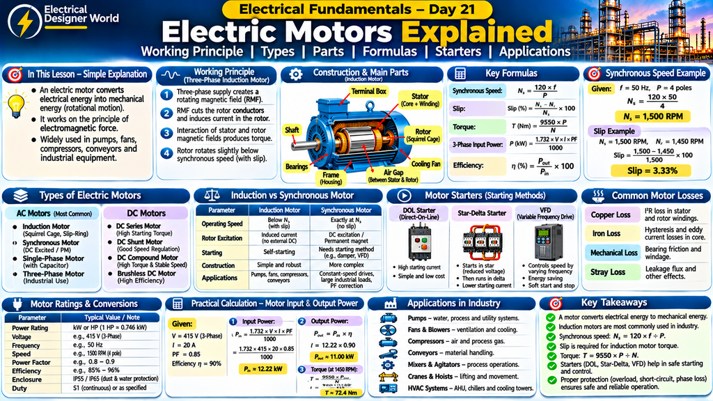
An electric motor converts electrical energy into mechanical energy. It makes machines rotate and perform useful work.
For example, the motor in a water pump rotates an impeller to move water. Motors in factories drive fans, compressors, conveyors, pumps and many other machines.
Electric motors are essential in industrial plants because they convert electrical power into the mechanical motion needed for production and everyday operations.
Introduction
Electric motors are among the most widely used machines in electrical engineering.
They are found in industrial plants, commercial buildings, hospitals, homes, power stations and infrastructure projects.
An electric motor works through the interaction of magnetic fields and electric current. This interaction produces torque, which causes the motor shaft to rotate.
In industrial applications, three-phase induction motors are particularly common because they are robust, reliable and relatively simple to maintain.
In this lesson, we will understand:
- What an electric motor is.
- How an electric motor works.
- Main parts of an electric motor.
- Different types of AC and DC motors.
- Induction and synchronous motors.
- Starters and motor control methods.
- Motor formulas and practical calculations.
- Motor losses and efficiency.
- Motor protection.
- Industrial applications and EPC design considerations.
1. What Is an Electric Motor?
An electric motor is an electrical machine that converts electrical energy into mechanical energy.
When electrical current flows through motor windings, magnetic fields are produced. The interaction between these magnetic fields generates a force and produces torque.
The torque rotates the motor shaft, which can drive equipment such as pumps, fans, compressors and conveyors.
Simple example:
When a water pump is switched ON, electrical power is supplied to its motor. The motor shaft rotates and drives the pump impeller, moving water through the piping system.
This is how electrical energy is converted into mechanical work.
2. Working Principle of an Electric Motor
Electric motors operate using the principle of electromagnetic force.
A current-carrying conductor placed in a magnetic field experiences a force. In a motor, the arrangement of conductors and magnetic fields produces rotational torque.
How Does a Three-Phase Induction Motor Work?
Step 1: Three-phase supply is connected
A three-phase AC supply is connected to the stator windings.
Step 2: Rotating magnetic field is produced
The three-phase stator currents create a rotating magnetic field inside the motor.
Step 3: Current is induced in the rotor
The rotating magnetic field cuts the rotor conductors and induces current in them.
Step 4: Rotor magnetic field is produced
The induced rotor current creates its own magnetic field.
Step 5: Torque is developed
The interaction between the stator magnetic field and rotor magnetic field produces torque.
Step 6: Motor shaft rotates
The rotor starts rotating and drives the connected mechanical load.
This is the basic working principle of a three-phase induction motor.
3. Main Parts of an Electric Motor
A typical industrial induction motor contains several important components.
1. Stator
The stator is the stationary part of the motor.
It contains the stator core and windings. When a three-phase supply is applied, the windings produce a rotating magnetic field.
2. Rotor
The rotor is the rotating part of the motor.
It is located inside the stator and rotates due to the torque produced by the interaction of magnetic fields.
Common rotor types include:
- Squirrel-cage rotor.
- Wound rotor or slip-ring rotor.
3. Stator Winding
The stator winding consists of insulated conductors arranged in slots in the stator core.
It produces the magnetic field when supplied with electrical current.
4. Rotor Bars
In a squirrel-cage motor, conducting bars are placed in rotor slots and connected by end rings.
These bars carry induced current and help produce rotor torque.
5. Shaft
The shaft transfers mechanical power from the motor to the driven equipment.
6. Bearings
Bearings support the shaft and allow smooth rotation while reducing friction.
7. Motor Frame
The motor frame provides mechanical support and protection for internal components.
8. Cooling Fan
The cooling fan helps remove heat generated during motor operation.
9. Terminal Box
The terminal box provides electrical connection points for the motor supply cables.
It may contain terminals marked U1, V1, W1, U2, V2 and W2 in a six-terminal three-phase motor.
10. Air Gap
The air gap is the small space between the stator and rotor.
It allows the rotor to rotate while magnetic flux links the stator and rotor.
4. Types of Electric Motors
Electric motors can be classified into two major groups:
- AC motors.
- DC motors.
A. AC Motors
AC motors operate using alternating current.
Common AC motor types include:
- Induction motors.
- Synchronous motors.
- Single-phase motors.
- Three-phase motors.
- Permanent magnet synchronous motors.
B. DC Motors
DC motors operate using direct current.
Common types include:
- DC series motor.
- DC shunt motor.
- DC compound motor.
- Brushless DC motor.
Each type has different operating characteristics and applications.
5. What Is an Induction Motor?
An induction motor is an AC motor in which rotor current is produced by electromagnetic induction rather than being supplied directly to the rotor in a conventional squirrel-cage design.
It is also called an asynchronous motor because its rotor normally runs at a speed slightly below synchronous speed when operating as a motor.
Types of Induction Motors
1. Squirrel-Cage Induction Motor
This is one of the most commonly used industrial motors.
Its rotor contains conducting bars connected by end rings.
Advantages:
- Simple construction.
- Robust design.
- Reliable operation.
- Low maintenance compared with many other motor types.
- Suitable for many industrial applications.
Applications include pumps, fans, blowers, compressors and conveyors.
2. Slip-Ring Induction Motor
A slip-ring induction motor has a wound rotor connected to slip rings.
External resistance can be introduced into the rotor circuit during starting to improve starting torque and control starting current.
Applications include certain cranes, hoists, mills and heavy-duty starting applications.
6. What Is a Synchronous Motor?
A synchronous motor is an AC motor that runs at synchronous speed when operating in synchronism with the rotating magnetic field.
Unlike an induction motor, its rotor magnetic field is produced using DC excitation or permanent magnets, depending on the design.
Characteristics
- Runs at synchronous speed.
- Speed is determined by supply frequency and number of poles.
- Does not operate with the normal induction-motor slip.
- May use DC excitation or permanent magnets.
- Can be used in applications requiring constant speed.
An overexcited wound-field synchronous motor can operate at a leading power factor and may be used for power factor correction.
Applications
- Large industrial compressors.
- Pumps.
- Mills.
- High-power constant-speed drives.
- Synchronous condensers for reactive power support.
7. Difference Between Induction Motor and Synchronous Motor
| Parameter | Induction Motor | Synchronous Motor |
|---|---|---|
| Operating speed | Slightly below synchronous speed in normal motoring operation | Runs at synchronous speed |
| Slip | Required for torque production | Zero in steady synchronous operation |
| Rotor field | Induced in a conventional induction rotor | Produced by DC excitation or permanent magnets |
| Starting | Common three-phase types are self-starting | Usually requires a suitable starting method |
| Construction | Generally simple and robust | Generally more complex |
| Applications | Pumps, fans, compressors and conveyors | Constant-speed and selected high-power applications |
8. Single-Phase and Three-Phase Motors
Single-Phase Motor
A single-phase motor operates using a single-phase AC supply.
It is commonly used where three-phase power is not available or where the required motor rating is relatively small.
Applications include:
- Domestic fans.
- Small water pumps.
- Washing machines.
- Small compressors.
- Household appliances.
Many single-phase induction motors use an auxiliary winding and a capacitor or another starting arrangement to produce starting torque.
Three-Phase Motor
A three-phase motor operates using a three-phase AC supply.
It is widely used in industrial applications because three-phase supply produces a rotating magnetic field and supports efficient motor operation.
Applications include:
- Industrial pumps.
- Compressors.
- Cooling tower fans.
- HVAC systems.
- Conveyor systems.
- Process equipment.
9. What Is Synchronous Speed?
Synchronous speed is the speed of the rotating magnetic field produced by the stator.
It depends on the supply frequency and the number of magnetic poles.
Formula
Ns = 120 × f ÷ P
Where:
- Ns = Synchronous speed in RPM.
- f = Supply frequency in hertz (Hz).
- P = Number of poles.
Practical Example
Suppose:
- Supply frequency = 50 Hz.
- Number of poles = 4.
Ns = 120 × 50 ÷ 4
Ns = 6000 ÷ 4
Ns = 1500 RPM.
Therefore, the synchronous speed is 1500 RPM.
Common Synchronous Speeds at 50 Hz
| Number of Poles | Synchronous Speed |
|---|---|
| 2 | 3000 RPM |
| 4 | 1500 RPM |
| 6 | 1000 RPM |
| 8 | 750 RPM |
| 10 | 600 RPM |
| 12 | 500 RPM |
These are theoretical synchronous speeds. An induction motor normally operates slightly below its synchronous speed under load.
10. What Is Slip in an Induction Motor?
Slip is the difference between the synchronous speed of the rotating magnetic field and the actual rotor speed, expressed as a percentage of synchronous speed.
An induction motor needs slip to induce rotor current and produce torque.
Slip Formula
Slip (%) = [(Ns − Nr) ÷ Ns] × 100
Where:
- Ns = Synchronous speed in RPM.
- Nr = Actual rotor speed in RPM.
Practical Example
Suppose:
- Synchronous speed = 1500 RPM.
- Actual rotor speed = 1450 RPM.
Slip = [(1500 − 1450) ÷ 1500] × 100
Slip = (50 ÷ 1500) × 100
Slip = 3.33%.
Therefore, the motor slip is approximately 3.33%.
11. What Is Motor Torque?
Torque is the twisting force that causes the motor shaft to rotate.
It is commonly measured in newton-metres (Nm).
Torque is important because it determines the motor’s ability to drive a mechanical load.
Examples:
- A pump motor requires torque to rotate the pump impeller.
- A conveyor motor requires torque to move material.
- A compressor motor requires torque to drive the compressor mechanism.
Torque Formula
For mechanical output power:
T = 9550 × P ÷ N
Where:
- T = Torque in Nm.
- P = Mechanical output power in kW.
- N = Shaft speed in RPM.
Practical Example
Suppose a motor has:
- Output power = 15 kW.
- Speed = 1450 RPM.
T = 9550 × 15 ÷ 1450
T ≈ 98.79 Nm.
Therefore, the motor produces approximately 98.79 Nm of torque at the stated output power and speed.
12. How Is Motor Power Calculated?
Motor power is commonly expressed in kilowatts (kW) or horsepower (HP).
Horsepower and Kilowatt Conversion
1 HP ≈ 0.746 kW.
1 kW ≈ 1.341 HP.
For example:
A 10 HP motor has an approximate mechanical output rating of:
10 × 0.746 = 7.46 kW.
Always check the motor nameplate to confirm the actual rated output.
Three-Phase Motor Input Power
For a balanced three-phase AC motor:
Input Power (kW) = 1.732 × V × I × PF ÷ 1000
Where:
- V = Line-to-line voltage in volts.
- I = Line current in amperes.
- PF = Power factor.
Motor Efficiency
Efficiency (%) = (Mechanical Output Power ÷ Electrical Input Power) × 100
The motor’s input power is normally greater than its mechanical output power because of electrical and mechanical losses.
13. Practical Motor Current Calculation
Suppose a three-phase motor has the following operating values:
- Supply voltage = 415 V.
- Line current = 20 A.
- Power factor = 0.85.
- Efficiency = 90%.
Calculate electrical input power and mechanical output power.
Step 1: Calculate Input Power
Input Power = 1.732 × V × I × PF ÷ 1000
= 1.732 × 415 × 20 × 0.85 ÷ 1000
Input Power ≈ 12.22 kW.
Step 2: Calculate Output Power
Output Power = Input Power × Efficiency
= 12.22 × 0.90
Output Power ≈ 11.00 kW.
Therefore, the motor delivers approximately 11 kW of mechanical output power under these operating conditions.
14. What Is a Motor Starter?
A motor starter is an electrical device or combination of devices used to start and stop a motor safely.
It may also provide protection against certain abnormal operating conditions.
Common motor starting methods include:
1. Direct-On-Line (DOL) Starter
A DOL starter connects the motor directly to the supply through a switching and protection arrangement.
Characteristics:
- Simple construction.
- Full supply voltage is applied at starting.
- High starting current compared with reduced-voltage starting methods.
- Suitable for motors and supply systems where direct starting is acceptable.
2. Star-Delta Starter
A star-delta starter starts a suitable six-terminal three-phase motor in star connection and then changes it to delta connection for normal running.
During star starting, each winding receives a lower voltage than it receives in delta operation.
This reduces starting current and starting torque compared with direct-on-line starting under comparable conditions.
3. Autotransformer Starter
An autotransformer starter applies reduced voltage to the motor during starting using an autotransformer.
It is used for certain larger motors where reduced-voltage starting is required.
4. Soft Starter
A soft starter uses power electronic devices to gradually increase the voltage applied to the motor during starting.
It helps reduce starting current and mechanical stress.
A soft starter does not normally provide the same continuous speed control as a variable frequency drive.
5. Variable Frequency Drive (VFD)
A VFD controls motor speed by changing the frequency and voltage supplied to the motor.
It is widely used in pumps, fans, compressors and process equipment where variable-speed operation is required.
15. What Is a Variable Frequency Drive (VFD)?
A Variable Frequency Drive is an electronic device that controls the speed of an AC motor by adjusting the supply frequency and voltage.
How Does a VFD Work?
A typical VFD has three main power conversion stages:
- Rectifier: Converts incoming AC supply into DC.
- DC link: Smooths and stores energy in the DC circuit.
- Inverter: Converts DC into variable-frequency AC output for the motor.
Applications of VFDs
- Water pumps.
- HVAC fans.
- Air compressors.
- Conveyor systems.
- Cooling tower fans.
- Process machinery.
VFDs can improve process control and reduce energy consumption in suitable variable-torque applications.
16. Motor Losses
Electric motors are not 100% efficient. Some electrical energy is lost during conversion into mechanical energy.
Common motor losses include:
1. Copper Loss
Copper losses occur due to resistance in the stator and rotor windings.
Formula:
Copper Loss = I² × R
2. Iron Loss
Iron losses occur in the motor magnetic core.
They include:
- Hysteresis loss.
- Eddy current loss.
3. Mechanical Loss
Mechanical losses occur due to bearing friction and air resistance.
4. Stray Load Loss
Stray losses occur due to leakage flux, harmonics and other load-dependent effects.
Reducing motor losses improves energy efficiency and reduces operating costs.
17. Motor Protection
Electric motors must be protected against faults and abnormal operating conditions.
Common motor protection functions include:
- Short-circuit protection.
- Overload protection.
- Earth-fault protection.
- Phase-loss protection.
- Phase-imbalance protection.
- Under-voltage protection.
- Locked-rotor or stall protection.
- Winding temperature protection.
- Bearing temperature protection, where required.
Motor protection requirements depend on motor rating, application, starting method, supply characteristics and project specifications.
18. Practical Applications of Motors in Industrial Plants
Electric motors are used in almost every industrial process.
1. Pumps
Motors drive pumps used for water supply, cooling water, process fluids and drainage systems.
2. Compressors
Motors drive air compressors, refrigeration compressors and process gas compressors.
3. Fans and Blowers
Motors operate ventilation fans, exhaust fans, cooling tower fans and air handling equipment.
4. Conveyors
Motors drive conveyor belts used for transporting materials in industrial plants.
5. Cooling Tower Systems
Motors operate cooling tower fans and other auxiliary equipment.
6. HVAC Systems
Motors are used in air handling units, pumps, fans and compressors.
7. Cranes and Hoists
Motors provide lifting and movement in material handling systems.
8. Industrial Process Equipment
Motors operate mixers, agitators, mills and other production machinery.
19. What Should an Electrical Engineer Check in a Motor Datasheet?
When reviewing motor vendor documents in an EPC project, check the following details:
| Parameter | What to Check |
|---|---|
| Rated power | Motor output in kW or HP |
| Voltage | Rated operating voltage |
| Frequency | 50 Hz or project-specified frequency |
| Phase | Single-phase or three-phase |
| Rated current | Full-load current |
| Speed | Rated RPM |
| Number of poles | 2, 4, 6, 8 or other |
| Power factor | Rated power factor |
| Efficiency | Rated efficiency |
| Duty | S1 or other specified duty |
| Insulation class | Winding insulation classification |
| Temperature rise | Permitted temperature rise |
| Enclosure | IP protection rating |
| Mounting | IM mounting arrangement |
| Starting method | DOL, star-delta, soft starter or VFD |
| Cooling | Cooling arrangement |
| Bearings | Bearing type and arrangement |
| Hazardous area | Gas group, temperature class and certification where required |
| Accessories | Space heater, RTDs, thermistors and other accessories where specified |
Always check the approved motor datasheet, vendor drawings, motor list, load list, single-line diagram and project specifications before finalising electrical design.
20. Electrical Safety Around Motors
Motors can present electrical, mechanical and thermal hazards.
Important precautions include:
- Only qualified and authorised personnel should work on electrical motors.
- Isolate the supply before maintenance.
- Follow lockout/tagout (LOTO) procedures.
- Verify absence of voltage using approved equipment.
- Check for unexpected automatic or remote starting.
- Ensure rotating parts are properly guarded.
- Follow correct earthing arrangements.
- Check alignment and coupling guards before operation.
- Follow manufacturer instructions for lubrication and maintenance.
- Use suitable PPE and follow site electrical safety procedures.
Motors controlled by VFDs may contain DC link capacitors that retain dangerous voltage after isolation. Follow the manufacturer’s specified discharge time and verify safe voltage before working on the equipment.
21. Frequently Asked Questions
1. What is the main function of an electric motor?
An electric motor converts electrical energy into mechanical energy.
2. What is the most commonly used motor in industries?
Three-phase squirrel-cage induction motors are widely used in industrial applications because of their robust construction and reliable operation.
3. What is the difference between an induction motor and a synchronous motor?
An induction motor normally operates below synchronous speed because it requires slip to produce torque. A synchronous motor runs at synchronous speed when operating in synchronism.
4. What is synchronous speed?
Synchronous speed is the speed of the rotating magnetic field in an AC motor.
Formula:
Ns = 120 × f ÷ P.
5. What is motor slip?
Slip is the percentage difference between synchronous speed and actual rotor speed in an induction motor.
6. What is the function of a motor starter?
A motor starter controls motor starting and stopping and may provide overload and other protective functions.
7. What is the function of a VFD?
A VFD controls AC motor speed by changing the frequency and voltage supplied to the motor.
8. Why are motors rated in kW?
The motor nameplate commonly specifies rated mechanical output power in kW or HP.
9. What does IP55 mean in a motor?
IP55 is an enclosure protection classification indicating protection against dust ingress at a level that does not interfere with satisfactory operation and protection against water jets from any direction under the specified test conditions.
10. Why is motor efficiency important?
Higher motor efficiency means less electrical input power is required for the same mechanical output, reducing energy consumption and operating costs.
22. Practice Questions
Test your understanding of electric motors.
Question 1: What is the main function of an electric motor?
A. Convert mechanical energy into electrical energy
B. Convert electrical energy into mechanical energy
C. Store electrical energy
D. Increase voltage
Question 2: Which part of a motor remains stationary?
A. Rotor
B. Shaft
C. Stator
D. Bearing
Question 3: Which motor is commonly used in industrial applications?
A. Three-phase squirrel-cage induction motor
B. Small shaded-pole motor
C. Universal motor only
D. Stepper motor only
Question 4: What is the synchronous speed formula?
A. Ns = 120 × f ÷ P
B. Ns = V ÷ I
C. Ns = I × R
D. Ns = P × V
Question 5: What is slip in an induction motor?
A. Difference between voltage and current
B. Difference between synchronous speed and rotor speed, expressed as a percentage
C. Motor output power
D. Winding resistance
Question 6: What is the function of a VFD?
A. Increase motor weight
B. Control motor speed by varying supply frequency
C. Store mechanical energy
D. Replace motor bearings
Question 7: Which starter uses reduced voltage by initially connecting suitable motor windings in star?
A. DOL starter
B. Star-delta starter
C. Soft starter
D. DC starter
Answers
- B – Convert electrical energy into mechanical energy.
- C – Stator.
- A – Three-phase squirrel-cage induction motor.
- A – Ns = 120 × f ÷ P.
- B – Difference between synchronous speed and rotor speed, expressed as a percentage.
- B – Control motor speed by varying supply frequency.
- B – Star-delta starter.
1. Natural Resources Canada – Electric Motors
For a deeper understanding of motor construction, operating principles, motor types, torque, speed and energy efficiency, refer to Natural Resources Canada – Electric Motors: Energy Efficiency Reference Guide.
2. Bureau of Energy Efficiency – Electric Motors
To learn more about induction motors, synchronous motors, DC motors, motor losses and industrial energy efficiency, refer to the Bureau of Energy Efficiency – Electric Motors Technical Guide.
3. Oregon State University – Motor Fundamentals
For additional learning about motor operating principles, components, efficiency, losses and speed control, explore Oregon State University – Motor Fundamentals.
4. IEEE – Induction Motors
To understand the electromagnetic working principle and construction of induction motors, refer to IEEE – Induction Motor Technical Overview.
Conclusion
Electric motors are essential components in industrial and commercial electrical systems.
They convert electrical energy into mechanical energy through the interaction of magnetic fields and electric current.
Understanding motor working principles, types, components, synchronous speed, slip, torque, starters, VFDs, losses and protection helps electrical engineers understand how industrial equipment operates.
For EPC electrical engineers, motor knowledge is particularly important when reviewing motor datasheets, calculating full-load current, selecting starters, understanding VFD applications and coordinating motor protection.
Continue learning with Electrical Designer World and strengthen your electrical engineering fundamentals step by step.
Continue the 30-Day Electrical Fundamentals Course
This lesson is part of the Electrical Fundamentals – 30-Day Learning Course.
- Previous lesson: Day 20 – Generators and Alternators.
- Current lesson: Day 21 – Electric Motors.
- Next lesson: Day 22 – Motor Starting Methods and Motor Protection.
Explore more electrical engineering lessons at Electrical Designer World.