
Harmonics in Electrical Systems – Causes, Effects, THD Calculation and Solutions
Table of Contents
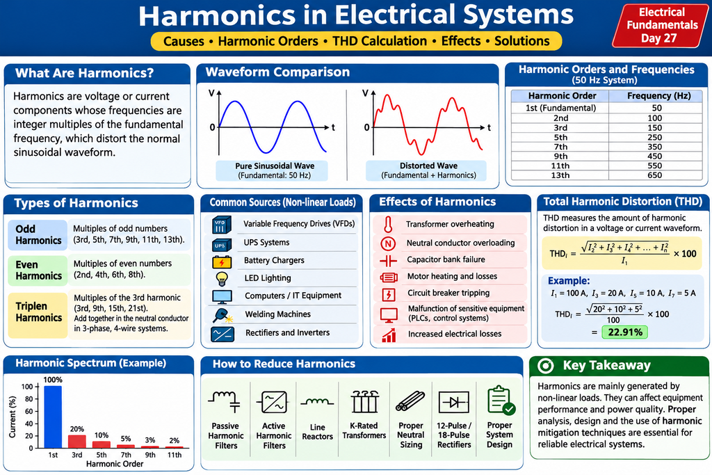
Simple Explanation of Electrical Harmonics
Imagine listening to a song with clear sound. Now imagine unwanted noise mixing with that sound. The quality becomes poor.
Electrical harmonics work in a similar way.
In a normal electrical system, voltage and current should have smooth sine waveforms. But equipment such as VFDs, UPS systems and inverters can create unwanted frequency components called harmonics.
These harmonics distort the normal waveform and can cause transformer overheating, neutral current problems, capacitor failures and increased electrical losses.
In simple words: Harmonics are unwanted frequency components in an electrical system that affect power quality and equipment performance.
Harmonics in electrical systems are one of the most important power quality problems in modern electrical installations. They are caused mainly by non-linear loads such as Variable Frequency Drives (VFDs), Uninterruptible Power Supplies (UPS), rectifiers, inverters and electronic equipment.
Harmonics distort the normal sinusoidal voltage and current waveforms. They can cause transformer overheating, excessive neutral current, capacitor bank failures, increased electrical losses and malfunctioning of sensitive electrical equipment.
In this lesson of our Electrical Fundamentals – Zero to Advanced series, we will understand harmonic orders, causes, effects, Total Harmonic Distortion (THD), practical calculations and harmonic reduction techniques used in industrial electrical systems.
1. What Are Harmonics in Electrical Systems?
In an ideal electrical power system, voltage and current waveforms are pure sinusoidal waves.
However, in practical electrical installations, certain electrical equipment draws current in a non-sinusoidal waveform. These distorted waveforms contain additional frequency components called harmonics.
Harmonics are frequency components that are integer multiples of the fundamental frequency.
In India, the standard electrical supply frequency is 50 Hz.
For example:
| Harmonic Order | Frequency |
|---|---|
| 1st (Fundamental) | 50 Hz |
| 2nd | 100 Hz |
| 3rd | 150 Hz |
| 5th | 250 Hz |
| 7th | 350 Hz |
| 9th | 450 Hz |
| 11th | 550 Hz |
| 13th | 650 Hz |
The fundamental frequency is the main operating frequency of the electrical supply.
When harmonic components combine with the fundamental waveform, the resulting voltage or current waveform becomes distorted.
2. Types of Harmonics
Electrical harmonics are generally classified into three important categories.
A. Odd Harmonics
Odd harmonics are multiples of odd numbers.
Examples include:
- 3rd harmonic – 150 Hz
- 5th harmonic – 250 Hz
- 7th harmonic – 350 Hz
- 9th harmonic – 450 Hz
- 11th harmonic – 550 Hz
- 13th harmonic – 650 Hz
Odd harmonics are commonly found in industrial electrical systems containing power electronic equipment.
B. Even Harmonics
Even harmonics are multiples of even numbers.
Examples include:
- 2nd harmonic – 100 Hz
- 4th harmonic – 200 Hz
- 6th harmonic – 300 Hz
- 8th harmonic – 400 Hz
Even harmonics are generally less common in symmetrical electrical systems. Their presence can indicate waveform asymmetry or particular operating conditions.
C. Triplen Harmonics
Triplen harmonics are multiples of the third harmonic.
Examples include:
- 3rd harmonic – 150 Hz
- 9th harmonic – 450 Hz
- 15th harmonic – 750 Hz
- 21st harmonic – 1050 Hz
Triplen harmonics are particularly important in three-phase, four-wire electrical distribution systems.
Unlike fundamental-frequency currents, triplen harmonic currents can add together in the neutral conductor instead of cancelling each other.
This can result in excessive neutral current and overheating.
3. What Causes Harmonics?
The main cause of harmonics is non-linear electrical loads.
A linear load draws current proportional to the applied voltage under normal operating conditions.
A non-linear load draws current in a distorted waveform even when the applied voltage is sinusoidal.
Common sources of harmonics include:
| Electrical Equipment | Harmonic Generation |
|---|---|
| Variable Frequency Drives | Rectifier and power electronic circuits |
| UPS Systems | Rectifier and inverter circuits |
| Battery Chargers | Electronic conversion circuits |
| LED Lighting | Electronic power supplies |
| Computers | Switched-mode power supplies |
| Welding Machines | Non-linear current consumption |
| Rectifiers | AC-to-DC conversion |
| Inverters | Power electronic switching |
Industrial plants containing a large number of VFDs and UPS systems require particular attention to harmonic distortion.
4. Effects of Harmonics on Electrical Equipment
Harmonics can affect the performance, efficiency and operating life of electrical equipment.
4.1 Transformer Overheating
Harmonic currents increase additional losses in transformer windings and structural components.
This can increase transformer temperature and reduce its expected operating life.
4.2 Neutral Conductor Overloading
Triplen harmonics generated by single-phase non-linear loads can add together in the neutral conductor.
This can result in excessive neutral current and overheating.
4.3 Capacitor Bank Failure
Harmonics can increase capacitor current and create electrical resonance conditions.
This may cause capacitor overheating, fuse operation and premature capacitor failure.
4.4 Motor Heating
Harmonic currents produce additional motor losses and can cause overheating, vibration and reduced efficiency.
4.5 Circuit Breaker Tripping
Distorted current waveforms and increased RMS current can contribute to unwanted protective-device operation.
4.6 Sensitive Equipment Malfunction
Sensitive equipment such as PLCs, control panels, communication systems and electronic instruments may experience operational disturbances.
4.7 Increased Electrical Losses
Harmonics increase electrical losses in cables, transformers, motors and other electrical equipment.
5. What Is Total Harmonic Distortion (THD)?
Total Harmonic Distortion (THD) is a measurement used to determine the amount of harmonic distortion present in an electrical voltage or current waveform.
It is expressed as a percentage.
Current THD Formula
THDᵢ = [√(I₂² + I₃² + I₄² + … + Iₙ²) / I₁] × 100
Where:
- I₁ = Fundamental current
- I₂ = Second harmonic current
- I₃ = Third harmonic current
- Iₙ = nth harmonic current
Voltage THD Formula
THDᵥ = [√(V₂² + V₃² + V₄² + … + Vₙ²) / V₁] × 100
Where:
- V₁ = Fundamental voltage
- V₂, V₃ and subsequent terms = Harmonic voltage components.
Practical THD Calculation Example
Consider an industrial electrical system with the following measured current values:
| Harmonic Order | Current |
|---|---|
| Fundamental | 100 A |
| 3rd Harmonic | 20 A |
| 5th Harmonic | 10 A |
| 7th Harmonic | 5 A |
Using the current THD formula:
THDᵢ = [√(20² + 10² + 5²) / 100] × 100
THDᵢ = [√(400 + 100 + 25) / 100] × 100
THDᵢ = [√525 / 100] × 100
THDᵢ = 22.91%
Therefore, the current Total Harmonic Distortion is approximately 22.91%.
This indicates that the harmonic current components have a combined RMS magnitude equal to 22.91% of the fundamental current.
6. How to Reduce Harmonics in Electrical Systems
Electrical engineers use different techniques to reduce harmonic distortion.
6.1 Passive Harmonic Filters
Passive harmonic filters consist of inductors, capacitors and sometimes resistors.
They are designed to reduce selected harmonic frequencies.
6.2 Active Harmonic Filters
Active harmonic filters use power electronic circuits to inject compensating currents into the electrical system.
They reduce harmonic currents and can respond to changing load conditions.
6.3 Line Reactors
Line reactors are inductors installed at the input of VFDs and other electrical equipment.
They help reduce current distortion and limit current peaks.
6.4 Harmonic-Designed Transformers
Transformers designed for harmonic-rich loads can withstand additional heating effects associated with harmonic currents.
6.5 Proper Neutral Conductor Sizing
Neutral conductors in three-phase, four-wire systems should be evaluated for triplen harmonic currents.
Their sizing must consider actual load conditions and applicable electrical standards.
6.6 Multi-Pulse Rectifiers
12-pulse and 18-pulse rectifier arrangements can reduce certain characteristic harmonics compared with conventional six-pulse rectifiers.
6.7 Proper Electrical System Design
During electrical system design, engineers should consider:
- Harmonic load assessment.
- Transformer selection.
- VFD and UPS specifications.
- Neutral conductor sizing.
- Capacitor bank selection.
- Harmonic filter requirements.
- Power quality analysis.
The appropriate mitigation method should be selected after conducting a harmonic study.
7. How Are Harmonics Measured?
Harmonics are measured using a Power Quality Analyzer.
This instrument helps electrical engineers identify and analyse:
- Voltage THD.
- Current THD.
- Individual harmonic magnitudes.
- Harmonic spectrum.
- Voltage and current waveforms.
- Power factor.
- Frequency variations.
- Voltage disturbances.
A harmonic spectrum displays the magnitude of individual harmonic orders.
For example, an engineer can identify whether the 3rd, 5th, 7th or 11th harmonic is contributing significantly to the distortion.
Measurements should be taken at suitable locations in the electrical distribution system, such as the main incomer, distribution panels and feeders supplying non-linear loads.
8. Practical Industrial Example
Consider an industrial plant containing:
- Five Variable Frequency Drives.
- Two UPS systems.
- LED lighting.
- Battery chargers.
- PLC control panels.
- Power factor correction capacitor banks.
After commissioning, the plant experiences the following problems:
- Transformer temperature increases.
- Neutral conductor carries excessive current.
- Capacitor bank fuses frequently operate.
- Sensitive control equipment experiences disturbances.
The electrical engineer suspects harmonic distortion.
A power quality analysis is performed, and significant harmonic currents are identified.
Based on the measurement results, the engineer evaluates the following mitigation measures:
- Installation of active harmonic filters.
- Review of VFD input arrangements.
- Transformer harmonic loading assessment.
- Neutral conductor capacity verification.
- Capacitor bank resonance assessment.
These measures help improve electrical system reliability and equipment performance.
Engineering Note: Harmonic filters should not be selected only based on connected load capacity. Actual harmonic measurements, system impedance, load variation and resonance studies must be considered.
9. Importance of Harmonic Studies in EPC Electrical Projects
Harmonic studies are important in Engineering, Procurement and Construction (EPC) projects.
They help electrical engineers evaluate the impact of non-linear loads on the electrical distribution network.
Typical engineering considerations include:
- Preparation of harmonic load lists.
- Identification of non-linear loads.
- Review of VFD and UPS harmonic data.
- Transformer harmonic loading assessment.
- Neutral conductor sizing.
- Capacitor bank and resonance assessment.
- Harmonic filter selection.
- Power quality compliance.
A proper harmonic study helps prevent equipment problems and improves the reliability of industrial power distribution systems.
10. Relevant Electrical Standards
Electrical engineers should refer to applicable standards when performing harmonic assessments.
Important references include:
- IEEE 519 – Recommended Practice and Requirements for Harmonic Control in Electric Power Systems.
- IEC 61000-2-4 – Compatibility levels in industrial plants for low-frequency conducted disturbances.
- IEC 61000-3-2 – Limits for harmonic current emissions for applicable equipment.
- IEC 61000-3-12 – Limits for harmonic currents produced by equipment connected to public low-voltage systems.
Official technical references:
Always verify the applicable edition, equipment scope and project specifications before applying harmonic limits.
11. Conclusion
Harmonics are an important power quality concern in modern electrical installations.
They are mainly generated by non-linear loads such as VFDs, UPS systems, rectifiers, inverters and electronic equipment.
Excessive harmonic distortion can cause transformer overheating, neutral conductor overloading, capacitor bank problems, motor heating and equipment malfunction.
Electrical engineers should understand harmonic orders, THD calculations, harmonic measurements and mitigation techniques to design reliable and efficient electrical distribution systems.
Remember: Identifying and controlling harmonics is an important part of modern electrical engineering and EPC project design.
12. Frequently Asked Questions (FAQs)
Q1. What are harmonics in electrical systems?
Harmonics are voltage or current components whose frequencies are integer multiples of the fundamental frequency. They distort normal sinusoidal waveforms.
Q2. What is the fundamental frequency in India?
The standard electrical supply frequency in India is 50 Hz.
Q3. What is the third harmonic of 50 Hz?
The third harmonic is 150 Hz (50 × 3).
Q4. What causes harmonics in electrical systems?
Non-linear loads such as VFDs, UPS systems, rectifiers, inverters, LED lighting and electronic power supplies generate harmonics.
Q5. What is THD in electrical engineering?
Total Harmonic Distortion (THD) measures the amount of harmonic distortion in a voltage or current waveform, expressed as a percentage of the fundamental component.
Q6. Why are third harmonics dangerous in neutral conductors?
Third-order and other triplen harmonic currents can add together in the neutral conductor instead of cancelling each other, potentially causing excessive neutral current.
Q7. How can harmonics be reduced?
Harmonics can be reduced using passive harmonic filters, active harmonic filters, line reactors, multi-pulse rectifiers and appropriate electrical system design.
Q8. Which instrument is used to measure harmonics?
A Power Quality Analyzer is commonly used to measure individual harmonic components, voltage THD and current THD.
Q9. What is the difference between voltage THD and current THD?
Voltage THD measures distortion in the voltage waveform, whereas current THD measures distortion in the current waveform.
Q10. Which harmonic orders are commonly found in industrial systems?
The 5th, 7th, 11th and 13th harmonic orders are commonly encountered in conventional six-pulse rectifier-based industrial installations.
Further Reading – External Resources
For a deeper understanding of electrical harmonics, power quality and harmonic mitigation, refer to these technical resources:
- Electrical Harmonics – Electrical Installation Guide (Schneider Electric)
https://www.electrical-installation.org/enwiki/Definition_of_harmonics - Power Harmonics Management – Electrical Installation Guide
https://www.electrical-installation.org/enwiki/Power_harmonics_management - Harmonic Sources – Eaton
https://www.eaton.com/us/en-us/products/controls-drives-automation-sensors/harmonics/harmonic-sources—what-causes-harmonics.html - IEEE Standards Association – IEEE 519 Harmonic Control Standard
https://standards.ieee.org/ - International Electrotechnical Commission (IEC)
https://www.iec.ch/
These resources provide additional technical information about harmonic distortion, power quality requirements, harmonic sources and mitigation techniques used in industrial electrical systems.
Continue Learning Electrical Fundamentals
This article is part of our structured Electrical Fundamentals – Zero to Advanced learning series.
Continue your electrical engineering journey with the following lessons: