
Day 25: Electrical Resonance – Series Resonance, Parallel Resonance and Resonant Frequency
Electrical Fundamentals – 30-Day Learning Course
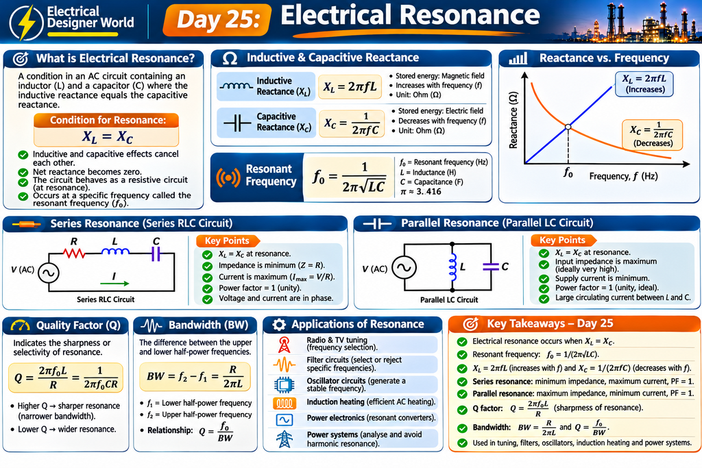
Simple Summary
Table of Contents
Electrical resonance occurs in an AC circuit when inductive reactance (XL) becomes equal to capacitive reactance (XC).
At this condition:
- The inductor and capacitor cancel each other’s reactive effects.
- The circuit behaves as a resistive circuit at resonance.
- The resonant frequency depends on inductance and capacitance.
- Series and parallel RLC circuits behave differently at resonance.
Let’s understand these concepts step by step.
1. What Is Electrical Resonance?
Electrical resonance is a condition in an AC circuit containing an inductor (L) and a capacitor (C), where their reactances become equal.
The basic condition is:
XL = XC
Where:
- XL = Inductive reactance in ohms (Ω).
- XC = Capacitive reactance in ohms (Ω).
At resonance, the net reactive effect becomes zero.
In simple words:
An inductor opposes changes in current, while a capacitor opposes changes in voltage. At a particular frequency, their reactances become equal and cancel each other in the circuit.
This frequency is called the resonant frequency.
2. Understand Inductor and Capacitor Behaviour
Before learning resonance, understand how inductors and capacitors behave in AC circuits.
Inductor (L)
An inductor stores energy in a magnetic field.
Its reactance is:
XL = 2 × π × f × L
Where:
- f = Frequency in hertz (Hz).
- L = Inductance in henry (H).
- XL = Inductive reactance in ohms (Ω).
Important: Inductive reactance increases when frequency increases.
Capacitor (C)
A capacitor stores energy in an electric field.
Its reactance is:
XC = 1 ÷ (2 × π × f × C)
Where:
- f = Frequency in hertz (Hz).
- C = Capacitance in farad (F).
- XC = Capacitive reactance in ohms (Ω).
Important: Capacitive reactance decreases when frequency increases.
Comparison
| Parameter | Inductor | Capacitor |
|---|---|---|
| Energy stored | Magnetic field | Electric field |
| Reactance | XL | XC |
| Frequency increases | Reactance increases | Reactance decreases |
| Current and voltage | Current lags voltage by 90° in an ideal inductor | Current leads voltage by 90° in an ideal capacitor |
3. Resonant Frequency
Resonant frequency is the frequency at which inductive reactance equals capacitive reactance.
The formula is:
f₀ = 1 ÷ (2 × π × √(L × C))
Where:
- f₀ = Resonant frequency in hertz (Hz).
- L = Inductance in henry (H).
- C = Capacitance in farad (F).
- π ≈ 3.1416.
This formula applies to an ideal LC circuit and gives the resonant frequency of a series RLC circuit as well as an ideal parallel LC circuit.
Practical Example
Given:
- Inductance = 0.1 H
- Capacitance = 100 μF
Find the resonant frequency.
Step 1: Convert capacitance into farads.
100 μF = 100 × 0.000001
C = 0.0001 F
Step 2: Apply the formula.
f₀ = 1 ÷ (2 × π × √(L × C))
f₀ = 1 ÷ (2 × 3.1416 × √(0.1 × 0.0001))
f₀ = 1 ÷ (6.2832 × 0.003162)
f₀ ≈ 50.3 Hz
Therefore, the resonant frequency is approximately 50.3 Hz.
4. Series Resonance
What Is Series Resonance?
Series resonance occurs in a series RLC circuit when the inductor, resistor and capacitor are connected in series and:
XL = XC
At resonance, the inductive and capacitive reactances cancel each other.
The impedance becomes minimum and equals the circuit resistance for a simple series RLC circuit.
Series Resonance Circuit
A series RLC circuit contains:
- Resistor (R)
- Inductor (L)
- Capacitor (C)
- AC supply
All three components are connected in one path.
Characteristics of Series Resonance
- Inductive reactance equals capacitive reactance.
- Net reactance becomes zero.
- Circuit impedance becomes minimum.
- Circuit impedance equals resistance (Z = R).
- Circuit current becomes maximum for a fixed supply voltage.
- Power factor becomes unity.
- Voltage and current are in phase at resonance.
Series RLC Impedance Formula
Z = √[R² + (XL − XC)²]
At resonance:
XL = XC
Therefore:
Z = R
Series Resonance Example
Given:
- Resistance = 10 Ω
- Inductance = 0.1 H
- Capacitance = 100 μF
- Supply voltage = 100 V
From our previous calculation:
Resonant frequency ≈ 50.3 Hz.
At resonance:
Z = R
Z = 10 Ω
Circuit current:
I = V ÷ Z
I = 100 ÷ 10
I = 10 A
Therefore, the circuit current at resonance is 10 A.
5. Parallel Resonance
What Is Parallel Resonance?
Parallel resonance occurs in a parallel RLC circuit when the inductive and capacitive effects cancel each other at a particular frequency.
In a simple ideal parallel LC circuit, the inductor and capacitor are connected in parallel.
At resonance:
XL = XC
The inductive and capacitive branch currents are equal in magnitude and opposite in phase.
Characteristics of Parallel Resonance
- Inductive and capacitive effects cancel at resonance.
- Input impedance becomes maximum in an ideal parallel LC circuit.
- Supply current becomes minimum in an ideal parallel LC circuit.
- Power factor is unity for an ideal lossless circuit.
- Large circulating currents may flow between the inductor and capacitor branches.
Important: Real parallel resonant circuits have losses and finite impedance. Their resonant frequency and impedance depend on the actual circuit configuration and component losses.
Series vs Parallel Resonance
| Parameter | Series Resonance | Parallel Resonance |
|---|---|---|
| Connection | R, L and C in series | L and C in parallel |
| Impedance at resonance | Minimum | Maximum in an ideal parallel LC circuit |
| Supply current | Maximum | Minimum in an ideal parallel LC circuit |
| Power factor | Unity for a simple series RLC circuit | Unity for an ideal lossless circuit |
| Main behaviour | Acceptor circuit | Rejector circuit |
6. Quality Factor (Q Factor)
What Is Q Factor?
The quality factor, also called Q factor, indicates the sharpness or selectivity of resonance.
A higher Q factor means a narrower and sharper resonance response.
For a simple series RLC circuit:
Q = (2 × π × f₀ × L) ÷ R
Alternatively:
Q = 1 ÷ (2 × π × f₀ × C × R)
Where:
- Q = Quality factor.
- f₀ = Resonant frequency.
- L = Inductance.
- C = Capacitance.
- R = Series resistance.
Example
Given:
- Resonant frequency = 50.3 Hz
- Inductance = 0.1 H
- Resistance = 10 Ω
Q = (2 × π × f₀ × L) ÷ R
Q = (2 × 3.1416 × 50.3 × 0.1) ÷ 10
Q ≈ 3.16
Therefore, the quality factor is approximately 3.16.
7. Bandwidth
What Is Bandwidth?
Bandwidth is the difference between the upper and lower half-power frequencies of a resonant circuit.
It indicates the frequency range over which the circuit responds significantly around resonance.
Formula:
BW = f₂ − f₁
Where:
- BW = Bandwidth in hertz.
- f₂ = Upper half-power frequency.
- f₁ = Lower half-power frequency.
For a simple series RLC circuit:
BW = R ÷ (2 × π × L)
Using our earlier example:
- R = 10 Ω
- L = 0.1 H
BW = 10 ÷ (2 × 3.1416 × 0.1)
BW ≈ 15.9 Hz
The relationship between Q factor and bandwidth is:
Q = f₀ ÷ BW
A higher Q factor generally means a narrower bandwidth.
8. Applications of Electrical Resonance
Electrical resonance is used in several electrical and electronic applications.
Radio and television tuning: Resonant circuits help select a particular signal frequency.
Communication systems: Resonance is used in frequency selection and filtering circuits.
Oscillator circuits: LC networks are used to determine oscillation frequency in suitable oscillator designs.
Filter circuits: Resonant circuits can be designed to select or reject particular frequency ranges.
Induction heating: Resonant power circuits are used in many induction-heating systems.
Power electronics: Resonant converters use resonant networks to achieve particular switching and energy-transfer characteristics.
9. Resonance in Electrical Power Systems
Resonance is important in power systems because inductors and capacitors are present in electrical networks.
For example:
- Transformers have inductance.
- Motors have inductive characteristics.
- Capacitor banks are used for power factor correction.
- Cables and transmission lines have distributed inductance and capacitance.
Under certain network conditions, resonance can amplify harmonic voltages or currents.
This can cause:
- Excessive capacitor current.
- Increased voltage distortion.
- Overheating of electrical equipment.
- Damage to capacitor banks.
- Unwanted operation of protective devices.
Engineers therefore consider harmonic analysis and resonance risks when designing capacitor banks and power factor correction systems.
10. Common Mistakes to Avoid
- Confusing inductive reactance with capacitive reactance.
- Forgetting to convert microfarads into farads.
- Assuming series and parallel resonance have the same impedance behaviour.
- Thinking resonance means zero current in every circuit.
- Ignoring resistance and losses in practical circuits.
- Assuming resonance is always beneficial.
- Forgetting that resonance can amplify harmonics in electrical networks.
11. Frequently Asked Questions
Q1. What is electrical resonance?
Electrical resonance is a condition in an AC circuit when inductive reactance equals capacitive reactance.
Q2. What is the formula for resonant frequency?
f₀ = 1 ÷ (2 × π × √(L × C))
Q3. What happens during series resonance?
Impedance becomes minimum, current becomes maximum and power factor becomes unity in a simple series RLC circuit.
Q4. What happens during parallel resonance?
In an ideal parallel LC circuit, input impedance becomes maximum and supply current becomes minimum.
Q5. What is Q factor?
Q factor indicates the sharpness or selectivity of resonance.
Q6. What is bandwidth?
Bandwidth is the difference between the upper and lower half-power frequencies.
Q7. Is electrical resonance dangerous?
Resonance can be harmful in power systems if it amplifies harmonic voltages or currents. Proper design and analysis help prevent problems.
12. Practice Questions
Test your understanding of today’s lesson.
- What is electrical resonance?
- What is the condition for resonance?
- What happens to inductive reactance when frequency increases?
- What happens to capacitive reactance when frequency increases?
- Write the formula for resonant frequency.
- What happens to impedance during series resonance?
- What happens to supply current during ideal parallel resonance?
- What does Q factor indicate?
- What is bandwidth?
- Why is resonance important in electrical power systems?
Answers
- A condition in an AC circuit where inductive and capacitive reactances become equal.
- XL = XC.
- It increases.
- It decreases.
- f₀ = 1 ÷ (2 × π × √(L × C)).
- It becomes minimum and equals R in a simple series RLC circuit.
- It becomes minimum in an ideal parallel LC circuit.
- The sharpness or selectivity of resonance.
- The difference between upper and lower half-power frequencies.
- It helps engineers understand and prevent unwanted amplification of harmonic voltages and currents.
Conclusion
Electrical resonance is an important concept in AC circuit analysis.
Remember these key points:
- Resonance occurs when XL = XC.
- Resonant frequency depends on inductance and capacitance.
- Series resonance produces minimum impedance and maximum current.
- Ideal parallel resonance produces maximum impedance and minimum supply current.
- Q factor describes resonance sharpness.
- Bandwidth describes the frequency range around resonance.
Understanding electrical resonance will help you analyse AC circuits, filters, communication systems and power-system harmonic problems.
Day 25 – Electrical Resonance: Understand series and parallel resonance, resonant frequency, inductive and capacitive reactance, Q factor and bandwidth through simple explanations and practical calculations. Read Day 25: Electrical Resonance.
Explore these additional learning resources to strengthen your understanding of AC circuits and resonance:
- All About Circuits – Alternating Current Textbook
- NPTEL – Engineering Courses
- Electrical Engineering Portal
Continue Learning – Electrical Fundamentals
- Previous lesson: Day 24 – Network Theorems
- Current lesson: Day 25 – Electrical Resonance
- Next lesson: Day 26 – Transient Response in Electrical Circuits
Explore the complete Electrical Fundamentals – Zero to Advanced course for the full learning sequence.