
Motor Starting Methods and Motor Protection Explained: DOL, Star-Delta, Soft Starter, VFD and Protection Devices
Day 22 – Electrical Fundamentals: 30-Day Learning Course
Simple Explanation
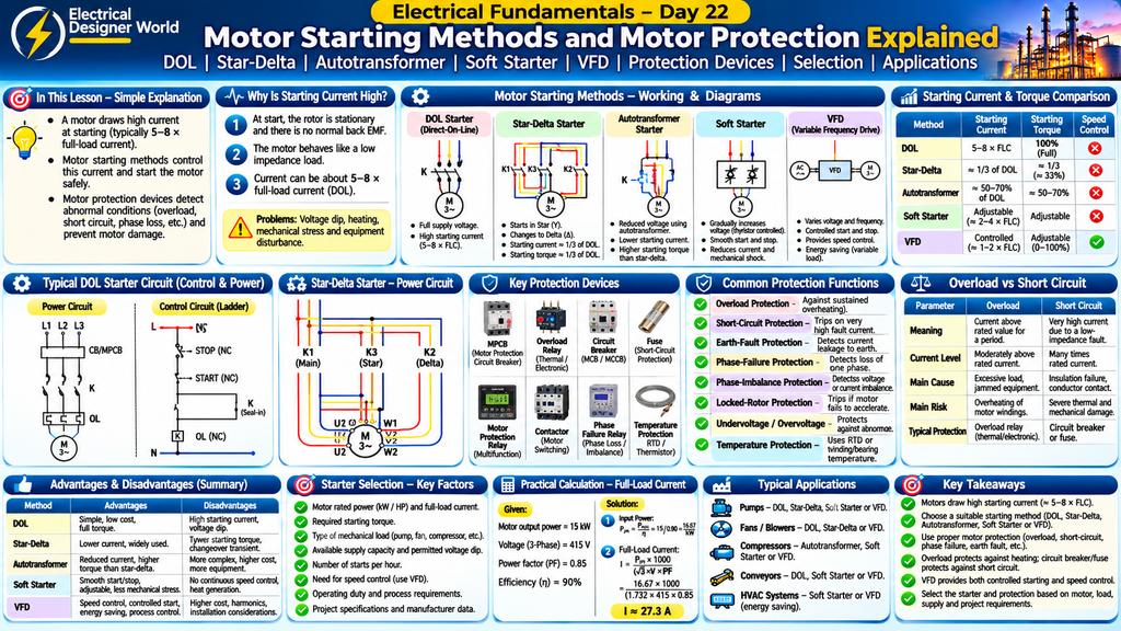
Table of Contents
An electric motor needs a suitable method to start safely. When a motor starts, it can draw a much higher current than it normally uses while running. This is called starting current.
Motor starting methods such as DOL, star-delta starters, soft starters and VFDs help control how a motor starts. Motor protection devices such as overload relays, circuit breakers and protective relays help protect the motor against faults and abnormal operating conditions.
These methods are important in industrial plants because motors operate pumps, compressors, fans, conveyors and many other machines.
Introduction
Electric motors are widely used in industrial and commercial electrical systems. However, starting a motor is not as simple as switching ON a light.
When an induction motor starts, it may draw several times its rated full-load current. This high starting current can cause voltage dips, electrical stress and mechanical shock if the starting method is not selected properly.
Motor protection is equally important. Motors can be damaged by overloads, short circuits, phase failures, earth faults, locked rotors and excessive temperature.
Electrical engineers therefore select suitable motor starting methods and protection devices based on motor rating, load characteristics, supply capacity and project requirements.
In this lesson, we will understand:
- Why motors draw high starting current.
- Different motor starting methods.
- DOL and star-delta starters.
- Autotransformer starters.
- Soft starters and VFDs.
- Motor protection devices.
- Overload, short-circuit and earth-fault protection.
- Motor protection relay functions.
- Practical industrial applications.
- Important EPC motor control design checks.
1. Why Does an Electric Motor Draw High Starting Current?
When a three-phase induction motor is at rest, its rotor is not yet rotating. The motor has not developed its normal running back EMF and the rotor circuit experiences conditions that allow a high current to flow when full supply voltage is applied.
As the motor accelerates, its operating conditions change and the current normally reduces towards its running value.
The current drawn during starting is called starting current or inrush current.
For many conventional induction motors, direct-on-line starting current can be approximately 5 to 8 times full-load current. The actual value depends on motor design, rating and manufacturer data.
Why Is High Starting Current a Problem?
High starting current can cause:
- Voltage dips in the electrical distribution system.
- Heating in motor windings.
- Electrical stress on cables and switchgear.
- Mechanical stress on couplings and driven equipment.
- Nuisance operation of protective devices if they are not selected correctly.
- Disturbances to other connected electrical loads.
Therefore, a suitable motor starting method must be selected.
2. What Is a Motor Starter?
A motor starter is an electrical device or combination of devices used to start, stop and control a motor.
Depending on its design, a motor starter may provide:
- Starting and stopping control.
- Overload protection.
- Short-circuit protection through coordinated protective devices.
- Undervoltage protection.
- Phase-failure or phase-imbalance protection.
- Remote and automatic control.
Common motor starting methods include:
- Direct-On-Line (DOL) starter.
- Star-Delta starter.
- Autotransformer starter.
- Primary resistance or reactor starter.
- Soft starter.
- Variable Frequency Drive (VFD).
3. What Is a Direct-On-Line (DOL) Starter?
A Direct-On-Line starter connects the motor directly to the supply through a switching and protection arrangement.
When the starter is switched ON, the motor receives the full rated supply voltage.
DOL is one of the simplest motor starting methods.
Main Components of a DOL Starter
A typical DOL starter arrangement may include:
- Circuit breaker or suitable short-circuit protective device.
- Contactor.
- Thermal or electronic overload relay.
- Start push button.
- Stop push button.
- Control circuit.
- Auxiliary contacts.
How Does a DOL Starter Work?
Step 1: The operator presses the START push button.
Step 2: The contactor coil is energised through the control circuit.
Step 3: The contactor main contacts close.
Step 4: Full supply voltage is applied to the motor.
Step 5: The motor starts rotating and accelerates towards its operating speed.
Step 6: The overload relay monitors the motor current and trips the control circuit if an overload condition occurs.
The STOP push button or a protective trip can de-energise the contactor coil and disconnect the motor.
Advantages of DOL Starter
- Simple construction.
- Low initial cost.
- Easy installation.
- Simple operation.
- Full starting torque is available at rated voltage.
Disadvantages of DOL Starter
- High starting current.
- Possible voltage dip in the supply system.
- High mechanical starting stress.
- Not suitable for every motor and load.
Applications
DOL starters are commonly used for suitable small and medium motors where the electrical supply can tolerate the starting current.
Examples include selected pumps, fans, small compressors and workshop machinery.
4. What Is a Star-Delta Starter?
A star-delta starter is a reduced-voltage starting method used with suitable three-phase squirrel-cage induction motors.
The motor starts with its stator windings connected in star. After the motor accelerates, the starter changes the winding connection to delta for normal operation.
This reduces the voltage applied to each winding during starting.
How Does a Star-Delta Starter Work?
Step 1: Starting in Star
The motor windings are connected in star.
Each winding receives a voltage equal to the line voltage divided by the square root of three.
Step 2: Motor Acceleration
The motor starts and accelerates with reduced starting voltage, current and torque.
Step 3: Changeover
After a set time or suitable control condition, the star contactor opens.
Step 4: Running in Delta
The delta contactor closes and the motor operates with its windings connected in delta at the intended rated operating voltage.
Main Components of a Star-Delta Starter
- Main contactor.
- Star contactor.
- Delta contactor.
- Overload relay.
- Timer or changeover controller.
- Short-circuit protective device.
- Electrical and mechanical interlocking arrangements.
Important Star-Delta Starting Relationship
For the same motor and supply voltage, under idealised comparison with DOL starting:
- Starting line current is approximately one-third of DOL starting line current.
- Starting torque is approximately one-third of DOL starting torque.
This is because each winding receives a reduced voltage during star starting.
Advantages
- Reduces starting current compared with DOL.
- Relatively simple and widely used.
- Lower cost than some electronic starting solutions.
- Suitable for certain pumps and fans.
Disadvantages
- Starting torque is also reduced.
- Changeover may cause a current and torque transient.
- Requires a motor with accessible winding terminals.
- Not suitable for every load.
- The motor must be suitable for delta running at the system supply voltage.
Applications
- Pumps.
- Fans.
- Blowers.
- Certain compressors.
- Other loads that can accelerate with reduced starting torque.
Important: Always check the motor nameplate and winding connection before selecting a star-delta starter. A motor intended to run in star at the available supply voltage must not be assumed suitable for star-delta starting.
5. What Is an Autotransformer Starter?
An autotransformer starter is a reduced-voltage starting method that uses an autotransformer to apply a lower voltage to the motor during starting.
Once the motor accelerates, the starter changes the circuit so the motor receives its normal supply voltage.
How Does It Work?
- The motor is initially supplied through an autotransformer.
- The autotransformer reduces the voltage applied to the motor.
- The motor starts with reduced current and torque.
- After the starting period, the starting circuit is disconnected.
- The motor is connected to the normal supply voltage.
Advantages
- Reduces motor starting current.
- Provides selectable reduced-voltage taps in suitable designs.
- Can provide higher starting torque than some other reduced-voltage methods at a comparable supply current.
Disadvantages
- More complex than DOL.
- Requires additional equipment and space.
- Higher initial cost.
- Requires suitable switching and protection arrangements.
Applications
Autotransformer starters may be used for larger motors and applications requiring reduced-voltage starting with a particular starting-torque requirement.
6. What Is a Soft Starter?
A soft starter is an electronic device that controls the voltage applied to an AC motor during starting and, depending on the design, stopping.
It uses power electronic devices, commonly thyristors, to gradually increase the applied motor voltage.
This helps reduce starting current and mechanical shock.
How Does a Soft Starter Work?
- The soft starter receives the start command.
- Its electronic devices control the voltage applied to the motor.
- The motor voltage gradually increases.
- The motor accelerates smoothly.
- The soft starter reaches full-voltage operation.
- Depending on the model, an internal or external bypass contactor may carry the running current.
Advantages
- Smooth starting.
- Reduced mechanical stress.
- Adjustable starting parameters.
- Reduced starting current compared with DOL in suitable settings.
- Can provide soft stopping in supported applications.
Disadvantages
- Does not normally provide continuous speed control like a VFD.
- Generates heat in its power electronic devices during operation.
- Requires correct selection and cooling.
- May not provide sufficient starting torque for every load.
Applications
- Pumps.
- Fans.
- Compressors.
- Conveyors.
- Industrial process equipment.
7. What Is a Variable Frequency Drive (VFD)?
A Variable Frequency Drive is an electronic device used to control the speed of an AC motor by varying the frequency and voltage supplied to it.
Unlike a conventional starter, a VFD can control motor speed during normal operation as well as during starting and stopping.
Main Stages of a VFD
A typical VFD has three main power conversion stages.
1. Rectifier
Converts incoming AC supply into DC.
2. DC Link
Smooths and stores energy in the DC circuit using capacitors and, depending on design, inductors.
3. Inverter
Converts DC into variable-frequency AC output for the motor.
How Does a VFD Work?
- AC power enters the VFD.
- The rectifier converts AC into DC.
- The DC link smooths the DC voltage.
- The inverter produces variable-frequency AC.
- The motor speed changes according to the supplied frequency and control settings.
Advantages of VFD
- Variable-speed control.
- Controlled starting and stopping.
- Reduced starting current in suitable applications.
- Better process control.
- Potential energy savings in variable-torque applications.
- Useful monitoring and control features.
Disadvantages of VFD
- Higher initial cost than basic starters.
- Produces electrical harmonics.
- May introduce additional motor heating and insulation stress depending on the installation.
- Requires suitable cable, earthing, EMC and motor selection considerations.
- Generates heat and requires appropriate cooling.
Applications
- Variable-speed pumps.
- HVAC fans.
- Cooling tower fans.
- Compressors.
- Conveyors.
- Process machinery.
8. Difference Between DOL, Star-Delta, Soft Starter and VFD
| Parameter | DOL | Star-Delta | Soft Starter | VFD |
|---|---|---|---|---|
| Starting voltage | Full voltage | Reduced voltage | Gradually controlled voltage | Controlled voltage and frequency |
| Starting current | High | Lower than DOL | Controlled and adjustable | Controlled by drive and load |
| Starting torque | High at rated voltage | Reduced | Adjustable, depends on settings | Can be controlled |
| Speed control during running | No | No | Normally no | Yes |
| Starting transition | Direct | Star-to-delta changeover | Smooth voltage ramp | Controlled frequency ramp |
| Complexity | Low | Medium | Medium | High |
| Typical application | Suitable small motors | Suitable fixed-speed motors | Smooth starting and stopping | Variable-speed applications |
The actual starting current and torque depend on the motor, load, supply and settings. Manufacturer data should be used for final selection.
9. What Is Motor Protection?
Motor protection means using electrical and thermal protection devices to prevent damage caused by abnormal operating conditions.
Motors can be damaged by:
- Overload.
- Short circuit.
- Earth fault.
- Phase failure.
- Phase imbalance.
- Locked rotor.
- Excessive starting frequency.
- Overheating.
- Undervoltage or overvoltage.
- Bearing or cooling problems.
A properly designed motor protection system detects abnormal conditions and disconnects the motor or initiates an alarm as appropriate.
10. Important Motor Protection Devices
1. Motor Protection Circuit Breaker (MPCB)
An MPCB is a protective device designed for motor circuits.
Depending on its design and settings, it can provide:
- Overload protection.
- Short-circuit protection.
- Phase-failure sensitivity.
It is commonly used in motor feeder arrangements.
2. Thermal Overload Relay
A thermal overload relay protects a motor against sustained overload current.
It uses the heating effect of current to detect an overload condition and trip the motor control circuit.
Important: A conventional thermal overload relay is not intended to provide short-circuit protection. A suitable circuit breaker or fuse must provide that protection.
3. Electronic Overload Relay
An electronic overload relay monitors motor current electronically.
Depending on the model, it may provide:
- Overload protection.
- Phase-loss protection.
- Phase-imbalance protection.
- Stall or locked-rotor protection.
- Ground-fault detection.
- Other configurable functions.
Always check the exact functions supported by the selected device.
4. Fuse
A fuse protects a circuit against excessive current by melting its element when the current exceeds its specified characteristics.
Motor circuits require suitable fuse selection and coordination with contactors and overload protection.
5. Contactor
A contactor is an electrically operated switching device used to switch motor power.
It is not, by itself, a complete motor protection device.
It is commonly used with suitable overload and short-circuit protective devices.
6. Motor Protection Relay
An electronic motor protection relay monitors electrical and, where provided, thermal parameters.
It can provide advanced protection functions for larger or more critical motors.
11. Common Motor Protection Functions
A. Overload Protection
Protects the motor against sustained excessive current that can cause winding overheating.
B. Short-Circuit Protection
Disconnects the motor circuit when a short-circuit fault causes very high current.
It is normally provided by suitable circuit breakers or fuses, coordinated with the motor starter and overload device.
C. Earth-Fault Protection
Detects current flowing to earth through an unintended path.
The protection method depends on the system earthing arrangement and the required sensitivity.
D. Phase-Failure Protection
Detects the loss of one phase in a three-phase supply.
Single phasing can cause excessive current and overheating in the remaining motor windings.
E. Phase-Imbalance Protection
Detects excessive differences between the three phase voltages or currents.
Voltage imbalance can produce significant current imbalance and additional motor heating.
F. Locked-Rotor Protection
Detects a motor that fails to accelerate or whose rotor remains stalled under abnormal conditions.
G. Undervoltage Protection
Detects voltage falling below the permitted operating level.
Undervoltage may cause motor performance problems and increased current under certain load conditions.
H. Overvoltage Protection
Detects voltage above the permitted operating level.
Excessive voltage can increase insulation stress and affect motor performance.
I. Winding Temperature Protection
Temperature sensors such as RTDs or thermistors can monitor winding temperature and provide alarm or trip signals.
J. Bearing Temperature Protection
Temperature sensors may be installed in bearings of larger or critical motors to detect abnormal heating.
12. Difference Between Overload and Short Circuit
Overload and short circuit are different electrical conditions and require suitable protection.
| Parameter | Overload | Short Circuit |
|---|---|---|
| Meaning | Motor draws more than its permitted load current for a period | Unintended low-impedance connection causes very high fault current |
| Current level | Usually moderately above rated current | Often many times rated current |
| Common cause | Excessive mechanical load, jammed equipment or abnormal operation | Insulation failure, damaged cable or conductor contact |
| Main risk | Excessive heating | Severe thermal and mechanical damage |
| Typical protection | Overload relay or motor thermal protection | Fuse or circuit breaker |
| Response | Usually time-delayed | Normally very fast, depending on protective device |
A motor feeder generally requires both overload and short-circuit protection, properly coordinated for the motor and installation.
13. What Is a Motor Protection Relay?
A motor protection relay is an electronic device that monitors a motor’s operating conditions and trips the motor when specified abnormal conditions are detected.
Depending on the relay model, available functions may include:
- Overload protection.
- Thermal overload model.
- Phase failure.
- Phase imbalance.
- Earth fault.
- Locked rotor.
- Excessive starting time.
- Undercurrent.
- Undervoltage.
- Overvoltage.
- Winding temperature.
- Bearing temperature.
- Starts-per-hour limitation.
Why Is a Motor Protection Relay Important?
It helps protect motors from damaging operating conditions and provides monitoring information for maintenance and plant operation.
Larger and critical motors often require more advanced protection than small motors.
14. How to Select a Motor Starter
The correct motor starting method depends on several factors.
Consider the following:
- Motor rated power in kW or HP.
- Motor full-load current.
- Starting current.
- Required starting torque.
- Type of mechanical load.
- Available supply capacity.
- Permitted voltage dip.
- Number of starts per hour.
- Required speed control.
- Operating duty.
- Environmental conditions.
- Project specifications and manufacturer recommendations.
Example: Selecting a Starter for Different Loads
| Application | Possible Starting Method | Main Consideration |
|---|---|---|
| Small water pump | DOL, if suitable | Supply capacity and starting current |
| Medium fixed-speed pump | Star-delta or soft starter | Starting torque and voltage dip |
| HVAC fan | Soft starter or VFD | Smooth starting or speed control |
| Variable-speed process pump | VFD | Flow and pressure control |
| Conveyor | DOL, soft starter or VFD | Starting torque and mechanical load |
| Large compressor | Depends on compressor design | Starting torque, unloading and process conditions |
These are examples, not fixed selection rules. Final selection requires motor and driven-equipment data.
15. Practical Example – Motor Full-Load Current
Suppose a three-phase motor has:
- Rated output power = 15 kW.
- Supply voltage = 415 V.
- Power factor = 0.85.
- Efficiency = 90%.
Calculate the approximate full-load current.
Step 1: Calculate Electrical Input Power
Input Power = Output Power ÷ Efficiency
Input Power = 15 ÷ 0.90
Input Power = 16.67 kW.
Step 2: Calculate Full-Load Current
Three-phase input power formula:
P = 1.732 × V × I × PF ÷ 1000
Rearranging:
I = P × 1000 ÷ (1.732 × V × PF)
Substitute:
I = 16.67 × 1000 ÷ (1.732 × 415 × 0.85)
I ≈ 27.3 A.
Therefore, the estimated full-load current is approximately 27.3 A.
This is a calculated estimate. Always use the actual motor nameplate current for final starter and protection selection.
16. What Should an Electrical Engineer Check in a Motor Starter Datasheet?
When reviewing starter or motor control centre vendor documents in an EPC project, check:
| Parameter | What to Check |
|---|---|
| Motor rating | kW or HP |
| Rated voltage | Motor operating voltage |
| Rated current | Motor full-load current |
| Starter type | DOL, star-delta, soft starter or VFD |
| Contactor rating | Suitable utilisation category and motor duty |
| Overload relay | Current range and trip class |
| Short-circuit protection | Breaker or fuse rating and coordination |
| Control voltage | Control circuit operating voltage |
| Starting method | Required control and sequence |
| Interlocking | Electrical and mechanical interlocking |
| Protection | Overload, phase failure, earth fault and other functions |
| Indication | ON, OFF, TRIP and fault indication |
| Remote control | PLC, DCS or local control requirements |
| Communication | Required communication protocol, if applicable |
| Enclosure | IP rating and installation environment |
| Cable connections | Incoming and outgoing cable requirements |
For a star-delta starter, also check the motor terminal arrangement and contactor switching sequence.
For a VFD, check input and output ratings, overload capability, harmonic considerations, cooling, cable requirements and motor compatibility.
17. Motor Protection and Starter Applications in EPC Projects
Motor starters and protection devices are commonly installed in Motor Control Centres (MCCs) and local control panels.
Typical industrial applications include:
1. Pump Motors
Used in cooling water pumps, process pumps, fire water pumps and utility pumps.
2. Fan Motors
Used in ventilation fans, exhaust fans and cooling tower fans.
3. Compressor Motors
Used in instrument air compressors and process air or gas compressors.
4. Conveyor Motors
Used for material handling and production lines.
5. HVAC Motors
Used in air handling units, chillers, pumps and ventilation systems.
6. Agitator and Mixer Motors
Used in chemical, water treatment and process industries.
The starter and protection arrangement must be suitable for the equipment duty, process requirements and electrical system design.
18. Electrical Safety During Motor Maintenance
Motor circuits can present electrical and mechanical hazards.
Follow these precautions:
- Isolate all relevant power sources.
- Follow lockout/tagout (LOTO) procedures.
- Verify absence of voltage using approved equipment.
- Check for remote and automatic starting commands.
- Secure rotating equipment against unexpected movement.
- Follow manufacturer instructions before opening motor terminal boxes.
- For VFD-driven motors, allow the specified DC-link discharge time and verify safe voltage before work.
- Never bypass overload or protective relays without an approved procedure.
- Use suitable PPE and follow site electrical safety rules.
Only authorised personnel should perform electrical maintenance and testing.
19. Frequently Asked Questions
1. Why does a motor draw high starting current?
At starting, the rotor is stationary and the motor has not developed its normal running back EMF. This allows a high current to flow when supply voltage is applied.
2. What is the difference between DOL and star-delta starters?
A DOL starter applies full supply voltage directly to the motor. A star-delta starter initially applies reduced winding voltage in star and then changes to delta for normal running.
3. Which starter reduces starting current?
Star-delta starters, autotransformer starters, soft starters and VFDs can reduce or control starting current when properly selected.
4. Does a star-delta starter reduce starting torque?
Yes. Under ideal comparison with DOL at the same supply voltage, star-delta starting torque is approximately one-third of DOL starting torque.
5. What is the function of an overload relay?
An overload relay protects the motor against sustained overload current that can cause excessive heating.
6. Does an overload relay protect against short circuits?
A conventional overload relay is not intended to provide short-circuit protection. A suitable fuse or circuit breaker is required.
7. What is the difference between a soft starter and a VFD?
A soft starter controls motor voltage during starting and often stopping. A VFD controls the motor’s supply frequency and voltage, allowing speed control during operation.
8. What is an MPCB?
A Motor Protection Circuit Breaker is a protective device designed for motor circuits and may provide overload and short-circuit protection, depending on its design.
9. Why is phase-failure protection important?
Loss of one phase can cause excessive current and overheating in the remaining phases of a three-phase motor.
10. Why is motor protection important?
Motor protection prevents or limits damage caused by overloads, short circuits, phase faults, overheating and other abnormal operating conditions.
20. Practice Questions
Test your understanding of motor starting methods and protection.
Question 1: What is the main reason for high starting current in an induction motor?
A. High bearing friction only
B. The motor is stationary and has not developed normal running back EMF
C. Low motor weight
D. High power factor
Question 2: Which starter connects the motor directly to the supply?
A. Star-delta
B. DOL
C. Soft starter
D. VFD
Question 3: In a star-delta starter, which connection is used during starting?
A. Delta
B. Star
C. Series
D. Parallel
Question 4: Which device controls motor speed by varying supply frequency?
A. Fuse
B. Contactor
C. VFD
D. Thermal overload relay
Question 5: What is the main function of an overload relay?
A. Increase motor speed
B. Protect against sustained overload current
C. Improve insulation
D. Reduce supply frequency
Question 6: Which device normally provides short-circuit protection in a motor feeder?
A. Contactor only
B. Overload relay only
C. Suitable circuit breaker or fuse
D. Start push button
Question 7: Which starting method is commonly used for smooth voltage-controlled starting?
A. Soft starter
B. Fuse
C. Isolator
D. Terminal block
Question 8: What does a phase-failure relay detect?
A. Bearing temperature only
B. Loss of one phase in a three-phase supply
C. Motor speed increase
D. Mechanical vibration only
Answers
- B – The motor is stationary and has not developed normal running back EMF.
- B – DOL.
- B – Star.
- C – VFD.
- B – Protect against sustained overload current.
- C – Suitable circuit breaker or fuse.
- A – Soft starter.
- B – Loss of one phase in a three-phase supply.
1. Schneider Electric – Motor Starters and Protection
For additional information about motor starters, overload protection, circuit breakers and motor control arrangements, explore Schneider Electric.
2. ABB – Motor Protection and Control
To learn more about industrial motor protection, contactors, overload relays, motor protection circuit breakers and motor control solutions, refer to ABB Electrification.
3. Siemens – Motor Control and Drives
For additional technical information about soft starters, variable frequency drives and industrial motor control, explore Siemens – Drives.
4. IEC – Electrical Equipment Standards
For information about international standards relevant to low-voltage switchgear, controlgear and motor protection, refer to the International Electrotechnical Commission (IEC).
Conclusion
Motor starting methods and motor protection are essential parts of industrial electrical design.
DOL, star-delta, autotransformer starters, soft starters and VFDs provide different ways to start and control electric motors.
Protection devices such as MPCBs, overload relays, circuit breakers, fuses and electronic motor protection relays help protect motors against overloads, short circuits, phase failures and other abnormal conditions.
For EPC electrical engineers, understanding motor starting and protection is important when reviewing motor datasheets, MCC drawings, starter schematics, motor lists and protection coordination requirements.
Continue learning with Electrical Designer World and strengthen your electrical engineering fundamentals step by step.
Continue the 30-Day Electrical Fundamentals Course
This lesson is part of the Electrical Fundamentals – 30-Day Learning Course.
- Previous lesson: Day 21 – Electric Motors.
- Current lesson: Day 22 – Motor Starting Methods and Motor Protection.
- Next lesson: Day 23 – Electrical Switchgear: ACB, MCCB, MCB, VCB and Protection Devices.
Explore more electrical engineering lessons at Electrical Designer World.