
Generators and Alternators Explained: Working Principle, Types, Parts, Formulas and Applications
Day 20 – Electrical Fundamentals: 30-Day Learning Course
Table of Contents
Simple Explanation
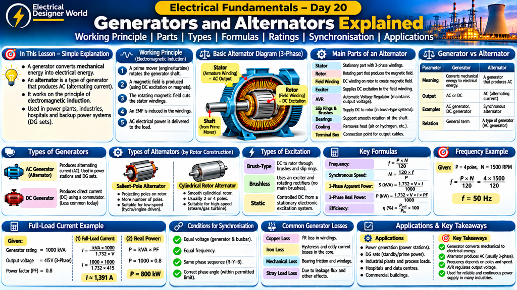
A generator is a machine that converts mechanical energy into electrical energy. An alternator is a type of generator that produces alternating current (AC).
For example, when a diesel engine rotates an alternator in an industrial generator set, the alternator produces electricity to supply equipment during a power failure. In power stations, turbines rotate large alternators to generate electricity for the electrical grid.
Generators and alternators are essential in power plants, factories, hospitals, commercial buildings and backup power systems.
Introduction
Electricity is required in almost every industry, building and infrastructure project. But how is electricity produced?
One of the most common methods is using an electrical generator.
Generators convert mechanical energy into electrical energy through electromagnetic induction. The mechanical energy may come from a diesel engine, steam turbine, water turbine, gas turbine or wind turbine.
An alternator is an AC generator. It is widely used in power stations and diesel generator sets.
In this lesson, we will understand:
- What a generator is.
- What an alternator is.
- The difference between generators and alternators.
- How electromagnetic induction produces electricity.
- Main parts of an alternator.
- Types of generators and alternators.
- Important formulas and calculations.
- Generator ratings, losses and efficiency.
- Excitation systems and automatic voltage regulators.
- Synchronisation and parallel operation.
- Protection and practical EPC applications.
1. What Is an Electrical Generator?
An electrical generator is a machine that converts mechanical energy into electrical energy.
It works on the principle of electromagnetic induction.
When a conductor experiences a changing magnetic flux linkage, an electromotive force (EMF) is induced in it.
The mechanical energy required to rotate the generator can come from different sources:
- Diesel engines.
- Steam turbines.
- Water turbines.
- Gas turbines.
- Wind turbines.
Generators are used to produce electricity in power stations and to provide backup power in buildings and industrial facilities.
Important: A generator does not create energy. It converts mechanical energy into electrical energy.
2. What Is an Alternator?
An alternator is an electrical generator that produces alternating current (AC).
It converts mechanical energy into AC electrical energy through electromagnetic induction.
Alternators are commonly used in:
- Thermal power stations.
- Hydroelectric power stations.
- Nuclear power stations.
- Diesel generator sets.
- Gas turbine generator sets.
- Wind power systems.
Most large power stations use three-phase synchronous alternators to generate electrical power.
The terms alternator and AC generator are often used interchangeably. In power-system engineering, a large alternator is commonly called a synchronous generator.
3. How Does a Generator Work?
A generator works on the principle of electromagnetic induction, discovered by Michael Faraday.
When a conductor cuts magnetic flux, or when the magnetic flux linking a conductor changes, an EMF is induced in the conductor.
Step-by-Step Working Principle
Step 1: Mechanical energy is supplied
A prime mover such as a diesel engine or turbine rotates the generator shaft.
Step 2: Magnetic field is established
A magnetic field is produced using permanent magnets or an electrically excited field winding, depending on the generator design.
Step 3: Relative motion occurs
The rotating magnetic field moves relative to the conductors in which voltage is induced.
Step 4: Voltage is generated
The changing magnetic flux linkage induces an EMF in the winding.
Step 5: Electrical power is delivered
When a load is connected, current flows through the external circuit and electrical power is supplied.
This is the basic working principle of an electrical generator.
4. Main Parts of an Alternator
A typical industrial alternator consists of several important components.
1. Stator
The stator is the stationary part of the alternator.
It contains the armature windings in which the output voltage is induced.
In most three-phase alternators, the stator contains three-phase windings arranged 120 electrical degrees apart.
2. Rotor
The rotor is the rotating part of the alternator.
It produces the magnetic field that links with the stator windings.
The rotor may use field windings supplied with DC excitation or permanent magnets in certain designs.
3. Field Winding
The field winding produces the magnetic field when supplied with DC current.
The strength of the magnetic field can be controlled by changing the excitation current.
4. Armature Winding
The armature winding is where the generated electrical voltage appears.
In most large alternators, the armature winding is located in the stationary stator.
5. Exciter
An exciter provides the excitation required to establish the rotor magnetic field.
Modern alternators may use brushless or static excitation systems.
6. Automatic Voltage Regulator (AVR)
The AVR controls the excitation system to maintain the alternator terminal voltage within the required operating range.
When the load changes, the AVR adjusts excitation to help regulate output voltage.
7. Slip Rings and Brushes
Some alternators use slip rings and brushes to supply DC excitation to the rotating field winding.
Brushless alternators use rotating rectifiers and do not require conventional field brushes for the main rotor excitation circuit.
8. Bearings
Bearings support the rotating shaft and allow smooth rotation.
9. Cooling System
The cooling system removes heat generated in the windings, core and other components.
Depending on the machine design, cooling may use air, hydrogen or other specified cooling arrangements.
10. Terminal Box
The terminal box provides the connection point for the alternator output cables or busbars.
5. How Does an Alternator Produce Three-Phase Electricity?
A three-phase alternator contains three stator windings positioned 120 electrical degrees apart.
When the rotor magnetic field rotates, it induces voltage in each winding.
The three generated voltages have the same frequency and are displaced from one another by 120 electrical degrees.
These are called:
- Phase R.
- Phase Y.
- Phase B.
Three-phase electricity is widely used in industrial power systems because it is suitable for transmitting and distributing electrical power and operating three-phase motors.
6. Difference Between Generator and Alternator
A generator is a general term for a machine that converts mechanical energy into electrical energy.
An alternator is a generator that produces AC.
| Parameter | Generator (General Term) | Alternator |
|---|---|---|
| Meaning | Converts mechanical energy into electrical energy | Produces alternating current |
| Output | Can be AC or DC, depending on design | AC |
| Working principle | Electromagnetic induction | Electromagnetic induction |
| Common types | AC generator and DC generator | Single-phase and three-phase alternator |
| Applications | Power generation and backup supply | Power stations and generator sets |
Remember: Every alternator is a generator, but not every generator is an alternator. A DC generator, for example, produces DC output using a commutator.
7. Types of Electrical Generators
Generators can be classified based on their electrical output and construction.
A. AC Generator
An AC generator produces alternating current.
Alternators used in power stations and industrial generator sets are examples of AC generators.
B. DC Generator
A DC generator produces direct current at its output terminals.
A commutator is used to convert the internally generated alternating voltage in the armature into unidirectional output.
DC generators are less common in modern large-scale power systems because electronic rectifiers can provide DC from AC supplies.
8. Types of Alternators Based on Rotor Construction
There are two common rotor designs.
1. Salient-Pole Alternator
A salient-pole alternator has projecting magnetic poles mounted on the rotor.
Characteristics:
- Usually has a large number of poles.
- Suitable for comparatively low-speed operation.
- Commonly used with hydro turbines and some engine-driven generator applications.
- Has a larger rotor diameter and shorter axial length in typical designs.
2. Cylindrical Rotor Alternator
A cylindrical rotor alternator has a smooth cylindrical rotor with field windings placed in slots.
Characteristics:
- Usually has two or four poles.
- Suitable for high-speed operation.
- Commonly used with steam and gas turbines.
- Designed for good mechanical strength at high rotational speeds.
9. Types of Alternators Based on Excitation
Excitation is the process of supplying current to the rotor field winding to produce the required magnetic field.
1. Brush-Type Excitation
In a brush-type excitation system, DC current is supplied to the rotating field winding through brushes and slip rings.
2. Brushless Excitation
A brushless excitation system uses an exciter and rotating rectifiers to supply DC to the main rotor field winding.
It reduces the need for conventional brushes and slip rings in the main excitation circuit.
3. Static Excitation
A static excitation system uses a stationary power electronic arrangement to provide controlled DC excitation to the rotor field winding, commonly through slip rings.
The actual excitation arrangement depends on the alternator design and manufacturer.
10. Important Generator and Alternator Formulas
The following formulas are important when understanding alternator operation and calculating generator ratings.
1. Frequency Formula
The frequency of a synchronous alternator depends on the number of poles and rotor speed.
f = P × N ÷ 120
Where:
- f = Frequency in hertz (Hz).
- P = Number of poles.
- N = Rotor speed in revolutions per minute (RPM).
2. Synchronous Speed Formula
N = 120 × f ÷ P
Where:
- N = Synchronous speed in RPM.
- f = Frequency in hertz.
- P = Number of poles.
3. Three-Phase Apparent Power
S (kVA) = 1.732 × Line Voltage × Line Current ÷ 1000
Where:
- S = Apparent power in kVA.
- Line voltage = Voltage between phases in volts.
- Line current = Line current in amperes.
4. Three-Phase Real Power
P (kW) = 1.732 × V × I × Power Factor ÷ 1000
Where:
- P = Real power in kW.
- V = Line-to-line voltage in volts.
- I = Line current in amperes.
5. Power Factor
Power Factor = kW ÷ kVA
Power factor indicates the relationship between real power and apparent power for a sinusoidal AC system.
6. Efficiency
Efficiency (%) = (Electrical Output Power ÷ Mechanical Input Power) × 100
This formula expresses the conversion efficiency when electrical output and mechanical input are measured in compatible power units.
11. Practical Example – Calculate Alternator Frequency
Suppose an alternator has:
- Number of poles = 4.
- Rotor speed = 1500 RPM.
Find the generated frequency.
Formula:
f = P × N ÷ 120
Substitute the values:
f = 4 × 1500 ÷ 120
f = 6000 ÷ 120
f = 50 Hz
Therefore, the alternator generates a frequency of 50 Hz.
Another Example
Suppose an alternator has:
- Number of poles = 2.
- Rotor speed = 3000 RPM.
f = 2 × 3000 ÷ 120
f = 50 Hz
Both examples produce 50 Hz, but the number of poles and rotational speeds are different.
12. Practical Example – Calculate Generator Current
Consider a three-phase generator with the following rating:
- Generator rating = 1000 kVA.
- Output voltage = 415 V.
- Power factor = 0.8.
Calculate the full-load current and real power.
Step 1: Calculate Full-Load Current
Formula:
I = kVA × 1000 ÷ (1.732 × Voltage)
I = 1000 × 1000 ÷ (1.732 × 415)
I ≈ 1,391 A
Therefore, the approximate full-load current is 1,391 A.
Step 2: Calculate Real Power
Real Power = kVA × Power Factor
Real Power = 1000 × 0.8
Real Power = 800 kW
Calculation Summary
| Parameter | Value |
|---|---|
| Generator rating | 1000 kVA |
| Output voltage | 415 V |
| Power factor | 0.8 |
| Full-load current | Approximately 1,391 A |
| Real power | 800 kW |
This example shows why generator ratings are commonly specified in kVA, while the usable real power in kW depends on the rated power factor.
Actual output capability also depends on temperature, altitude, cooling, operating conditions and the manufacturer’s rating.
13. What Is an Automatic Voltage Regulator (AVR)?
An Automatic Voltage Regulator is an important part of many alternator systems.
Its main function is to regulate the generator terminal voltage by controlling the excitation current.
How Does an AVR Work?
- The AVR senses the alternator output voltage.
- It compares the measured voltage with the reference voltage.
- If the voltage changes, the AVR adjusts the excitation.
- The magnetic field strength changes.
- The alternator terminal voltage is regulated.
The AVR helps maintain stable voltage when the generator load changes.
The actual response depends on the alternator, excitation system and AVR design.
14. What Is a Generator Set (DG Set)?
A generator set, commonly called a DG set, combines an engine and an electrical generator to produce electricity.
A typical diesel generator set includes:
- Diesel engine.
- Alternator.
- Fuel tank and fuel system.
- Cooling system.
- Lubrication system.
- Starting battery and starter motor.
- Control panel.
- Circuit breaker.
- Exhaust system.
- Base frame and vibration isolators.
- Acoustic enclosure, where specified.
How Does a DG Set Work?
- The engine starts using the battery and starter system.
- The engine rotates the alternator shaft.
- The alternator generates electrical power.
- The AVR regulates the output voltage.
- The control panel monitors the generator parameters.
- The circuit breaker connects the generator to the load when operating conditions and switching arrangements permit.
DG sets are commonly used as standby, prime or continuous power sources, depending on their ratings and manufacturer specifications.
15. What Are Generator Ratings?
Generator ratings indicate the electrical output that a generator can supply under specified operating conditions.
Common rating terms include:
1. kVA Rating
The apparent power rating of the generator.
2. kW Rating
The real power output rating at the specified power factor.
3. Power Factor
The rated power factor is used to relate the kVA and kW ratings.
For example:
1000 kVA × 0.8 = 800 kW.
4. Voltage Rating
The rated output voltage, such as 415 V or another specified voltage.
5. Frequency Rating
The rated output frequency, commonly 50 Hz in India.
6. Phase
Generators may be single-phase or three-phase, depending on their application.
7. Speed
The rated rotational speed in RPM.
8. Duty Rating
Common generator duty categories include:
- Standby.
- Prime.
- Continuous.
These ratings have different operating definitions and permitted loading conditions. Always check the manufacturer’s datasheet and applicable rating standard rather than treating them as interchangeable.
16. What Is Generator Synchronisation?
Synchronisation is the process of connecting an alternator to an energised electrical busbar or power system after matching the required electrical conditions.
Before connecting two AC sources in parallel, important conditions must be checked.
Conditions for Synchronisation
- Equal voltage: The incoming generator voltage should match the busbar voltage within the permitted limits.
- Equal frequency: The incoming generator frequency should match the system frequency.
- Same phase sequence: The phase sequence must be identical.
- Correct phase angle: The phase angle difference between corresponding voltages must be within the permitted synchronising limit.
A synchroscope or an approved automatic synchronising system may be used to assist with synchronisation.
Incorrect synchronisation can cause severe electrical and mechanical stress.
17. Why Are Generators Operated in Parallel?
In large industrial plants and power stations, multiple generators may operate in parallel.
Advantages include:
- Improved reliability.
- Greater total available capacity.
- Better flexibility during maintenance.
- Ability to share loads.
- Easier expansion of generation capacity.
- Improved operational flexibility.
When generators operate in parallel, real power sharing is mainly controlled by the prime mover and its governor, while reactive power sharing is influenced by excitation and voltage control.
Proper synchronisation, load sharing and protection are essential.
18. What Are Generator Losses?
Generators are not 100% efficient. Some input mechanical energy is lost during conversion into electrical energy.
Common losses include:
1. Copper Loss
Copper loss occurs due to resistance in the stator and rotor windings.
Formula:
Copper Loss = I² × R
2. Iron Loss
Iron losses occur in the magnetic core.
They include:
- Hysteresis loss.
- Eddy current loss.
3. Mechanical Loss
Mechanical losses occur due to bearing friction and windage.
4. Stray Load Loss
Stray losses occur due to leakage flux and other load-dependent effects.
Reducing losses improves generator efficiency and reduces operating costs.
19. Generator Protection
Generators require suitable protection against electrical faults and abnormal operating conditions.
Common protection functions include:
- Overcurrent protection.
- Earth-fault protection.
- Differential protection.
- Reverse power protection.
- Under-voltage protection.
- Over-voltage protection.
- Under-frequency protection.
- Over-frequency protection.
- Loss-of-excitation protection.
- Negative phase-sequence protection.
- Stator and bearing temperature protection.
- Overspeed protection.
The protection scheme depends on generator size, voltage level, grounding arrangement, operating mode and project requirements.
20. Practical Applications in EPC Electrical Projects
Generators and alternators are important in industrial and infrastructure projects.
1. Emergency Power Supply
DG sets supply backup power to essential equipment during a normal utility supply failure.
2. Hospitals
Generators provide backup power to essential hospital systems and critical services.
3. Industrial Plants
Generators may supply standby or prime power to motors, pumps, compressors and process equipment.
4. Data Centres
Generator systems support backup power arrangements for critical IT infrastructure.
5. Power Stations
Large alternators convert turbine mechanical energy into electrical power.
6. Construction Sites
Portable generators supply temporary power to construction equipment, lighting and site facilities.
7. Commercial Buildings
DG sets may supply selected emergency and essential electrical loads.
21. What Should an Electrical Engineer Check in a Generator Datasheet?
When reviewing generator vendor documents in an EPC project, check the following parameters:
| Parameter | What to Check |
|---|---|
| Rated capacity | kVA and kW |
| Rated voltage | Generator output voltage |
| Frequency | 50 Hz or project-specified frequency |
| Power factor | Rated power factor |
| Phase | Single-phase or three-phase |
| Speed | Rated RPM |
| Alternator type | Synchronous or other specified design |
| Winding connection | Star or delta, as specified |
| Excitation | Brushless, static or other arrangement |
| AVR | Type and voltage regulation details |
| Insulation class | Winding insulation specification |
| Temperature rise | Permitted temperature rise |
| Cooling | Cooling arrangement |
| Short-circuit capability | Manufacturer’s specified fault performance |
| Duty rating | Standby, prime or continuous |
| Protection | Generator protection functions |
| Enclosure | Open, weatherproof or acoustic enclosure |
| Fuel consumption | At specified load conditions, for engine-driven sets |
Always review the approved generator datasheet, alternator datasheet, control panel drawings, single-line diagram and project specifications before finalising the design.
22. Electrical Safety Around Generators
Generators can produce dangerous voltages and high fault currents.
Important safety precautions include:
- Only qualified and authorised personnel should operate generators.
- Never connect a generator directly to a utility supply without an approved transfer and synchronising arrangement.
- Follow isolation and lockout/tagout procedures before maintenance.
- Verify absence of voltage using approved equipment.
- Ensure proper earthing and neutral arrangements.
- Never operate a generator in an enclosed space without suitable exhaust arrangements.
- Keep fuel away from hot surfaces and ignition sources.
- Follow manufacturer instructions for starting, loading and shutdown.
- Use suitable PPE and follow site electrical safety procedures.
- Ensure protective devices and emergency shutdown systems are functional.
Generator installation and connection must follow applicable electrical regulations, project requirements and manufacturer’s instructions.
23. Frequently Asked Questions
1. What is the difference between a generator and an alternator?
A generator is a general machine that converts mechanical energy into electrical energy. An alternator is a generator that produces AC electricity.
2. What is the working principle of an alternator?
An alternator works on electromagnetic induction. A changing magnetic flux linking the stator windings induces an AC voltage.
3. Why is DC excitation required in an alternator?
DC excitation creates the magnetic field in the rotor of a conventional wound-field alternator.
4. What is the function of an AVR?
An AVR regulates alternator output voltage by controlling the excitation system.
5. Why are generators rated in kVA?
Generators are commonly rated in kVA because their current and voltage ratings determine apparent power capacity. The real power in kW depends on power factor.
6. What determines alternator frequency?
Alternator frequency depends on rotor speed and the number of magnetic poles.
7. What is the frequency of a 4-pole alternator running at 1500 RPM?
Using f = P × N ÷ 120:
f = 4 × 1500 ÷ 120.
Frequency = 50 Hz.
8. What is generator synchronisation?
Synchronisation is the process of matching voltage, frequency, phase sequence and phase angle before connecting a generator to an energised busbar.
9. What is a DG set?
A DG set is a diesel generator set consisting mainly of a diesel engine and an alternator, along with supporting systems.
10. Can an alternator produce DC?
An alternator naturally produces AC. Rectifiers can be used to convert its AC output into DC.
24. Practice Questions
Test your understanding of generators and alternators.
Question 1: What is the main function of an electrical generator?
A. Convert electrical energy into heat
B. Convert mechanical energy into electrical energy
C. Increase electrical resistance
D. Store electrical energy
Question 2: What is an alternator?
A. DC generator
B. AC generator
C. Transformer
D. Motor
Question 3: Which part of an alternator contains the output armature winding in most large machines?
A. Rotor
B. Stator
C. Bearing
D. Shaft
Question 4: What is the frequency formula for a synchronous alternator?
A. f = P × N ÷ 120
B. f = V ÷ I
C. f = I × R
D. f = P × V
Question 5: What is the function of an AVR?
A. Control fuel consumption
B. Regulate generator voltage
C. Increase engine speed only
D. Stop current flow
Question 6: What are the important conditions for synchronising an alternator?
A. Same voltage only
B. Same frequency only
C. Same phase sequence only
D. Voltage, frequency, phase sequence and phase angle must be matched
Question 7: What is the frequency of a 2-pole alternator running at 3000 RPM?
A. 25 Hz
B. 50 Hz
C. 60 Hz
D. 100 Hz
Answers
- B – Convert mechanical energy into electrical energy.
- B – AC generator.
- B – Stator.
- A – f = P × N ÷ 120.
- B – Regulate generator voltage.
- D – All four conditions must be matched.
- B – 50 Hz.
1. Bharat Skills – Alternator Working Principle
To understand how an alternator works, how it generates AC voltage and how frequency depends on rotor speed and the number of poles, refer to Bharat Skills – Alternator Principle and Frequency.
2. IEEE – Alternators
For additional technical information about alternator construction, excitation systems, synchronous generators and their applications, explore IEEE Technology Navigator – Alternators.
3. Open Electrical Engineering Learning Resource
To explore synchronous generator operation, rotor speed, frequency and three-phase generation, refer to Universal Curriculum – Synchronous Generator Operation.
Conclusion
Generators and alternators are essential machines in modern electrical power systems.
A generator converts mechanical energy into electrical energy, while an alternator specifically produces alternating current through electromagnetic induction.
Understanding their working principles, parts, types, formulas, ratings, excitation systems, synchronisation and protection helps electrical engineers understand how electrical power is generated and supplied to industrial and commercial loads.
For EPC electrical engineers, generator knowledge is especially important when reviewing generator datasheets, calculating full-load current, understanding kVA and kW ratings, checking alternator specifications and coordinating generator protection.
Continue learning with Electrical Designer World and strengthen your electrical engineering fundamentals step by step.
Continue the 30-Day Electrical Fundamentals Course
This lesson is part of the Electrical Fundamentals – 30-Day Learning Course.
- Previous lesson: Day 19 – Transformers.
- Current lesson: Day 20 – Generators and Alternators.
- Next lesson: Day 21 – Motors: Working Principle, Types and Applications.
Explore more electrical engineering lessons at Electrical Designer World.