
How to Read a Motor Feeder in an Electrical SLD
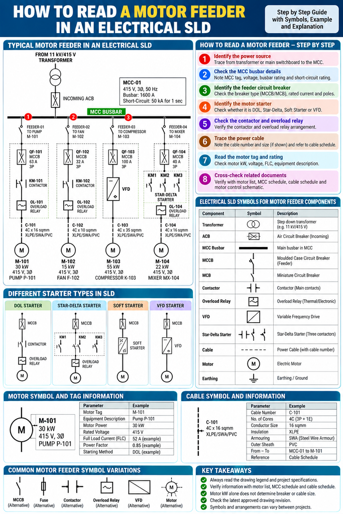
Table of Contents
How to read a motor feeder in an electrical SLD is an important skill for electrical designers working in Engineering, Procurement, and Construction (EPC) projects. A Single Line Diagram (SLD) shows how electrical power is distributed from a source to different electrical loads, including motors, pumps, fans, and compressors.
By learning how to read a motor feeder, you can identify the Motor Control Centre (MCC), feeder circuit breaker, motor starter, overload protection, motor rating, and cable connection.
In this practical guide, we will explain the main motor feeder components, how to trace the power path, and how to connect SLD information with the motor list and cable schedule.
If you are new to electrical drawings, start with our Electrical Designer World website for electrical engineering learning resources.
What Is a Motor Feeder in an Electrical SLD?
A motor feeder is an electrical circuit that supplies power from a distribution system, such as an MCC or switchboard, to an electric motor.
A typical low-voltage motor feeder may include:
- MCC busbar
- Feeder circuit breaker or fused protective device
- Contactor or motor controller
- Overload relay or electronic motor protection
- Power cable
- Motor and driven equipment
The actual components depend on the motor rating, starting method, protection requirements, and project specifications.
In an electrical SLD, these components are represented using simplified symbols and equipment tags. A single-line representation shows the main electrical connections without drawing every conductor separately.
Why Is Reading a Motor Feeder Important for EPC Electrical Designers?
Reading a motor feeder helps electrical designers understand the relationship between power distribution, motor control, protection, and cable design.
1. Understand the electrical power path
You can trace the electrical supply from the transformer or switchboard to the MCC and then to the individual motor.
2. Identify protection devices
You can identify the circuit breaker, fuse, overload relay, or other protection devices associated with the motor feeder.
3. Support cable sizing and cable schedules
The SLD provides important information about the source, destination, and motor identification. The approved motor data and design calculations are then used to establish cable requirements.
4. Coordinate electrical documents
The motor tag and feeder identification help you cross-check information between the SLD, motor list, MCC schedule, cable schedule, and motor control schematic.
5. Support electrical design reviews
Understanding the motor feeder helps you identify missing ratings, inconsistent tags, and information that needs verification before design approval.
Main Components of a Motor Feeder in an Electrical SLD
Before learning how to read a motor feeder, understand the purpose of each major component.
1. MCC Busbar
The Motor Control Centre busbar distributes electrical power to multiple outgoing motor feeders and other electrical loads.
In an SLD, the busbar is usually represented by a horizontal line with several outgoing branches.
Typical MCC information includes:
- MCC identification number
- Rated voltage
- Number of phases
- Busbar current rating
- Short-circuit withstand rating
For example, an MCC may be rated at 415 V, three-phase, with a 1600 A busbar. These are illustrative values; always verify actual project ratings.
2. Motor Feeder Circuit Breaker
The feeder circuit breaker provides switching and overcurrent protection according to the designed protection arrangement.
Common devices include:
- MCCB: Moulded Case Circuit Breaker
- MCB: Miniature Circuit Breaker, where suitable
- ACB: Air Circuit Breaker, commonly used for larger distribution applications
- VCB: Vacuum Circuit Breaker, commonly used in medium-voltage systems
When reading the SLD, check the breaker tag, rated current, number of poles, trip settings where shown, and interrupting capacity.
The breaker rating must not be selected using the motor kW rating alone. The design must consider motor current, starting characteristics, available fault current, cable protection, and coordination requirements.
3. Motor Starter
A motor starter controls how the motor starts and stops.
Common starting methods include:
- Direct-On-Line (DOL) starter
- Star-delta starter
- Soft starter
- Variable Frequency Drive (VFD)
A DOL starter connects the motor directly to the supply during starting. A star-delta starter changes the motor winding connection during starting. A soft starter controls the voltage during starting, while a VFD controls motor speed by varying the supply frequency.
The SLD may identify the starter type using a label or equipment designation. Refer to the motor control schematic when additional details are required.
4. Contactor
A contactor is an electrically operated switching device used to connect or disconnect the motor supply.
In a conventional DOL starter, the contactor operates in response to the motor control circuit.
A contactor is not a substitute for the required short-circuit and overload protection devices.
5. Overload Relay
An overload relay protects the motor against sustained overload conditions when correctly selected and applied.
It normally operates through the motor control circuit to disconnect the motor when an overload condition is detected.
The overload relay and circuit breaker have different functions. The complete protection arrangement must be designed to provide the required protection for the motor and its circuit.
6. Motor Symbol and Motor Tag
A motor is commonly represented by a circular symbol containing the letter M, although the exact symbol depends on the drawing convention.
A motor feeder may display information such as:
- Motor tag number
- Equipment description
- Motor power in kW or HP
- Rated voltage
- Full-load current
- Power factor
- Efficiency
- Starting method
For example:
M-101 | 30 kW | 415 V | Three-phase
This information identifies the motor and provides its basic rating details. It does not, by itself, determine the required breaker or cable size.
For more information about standardized electrical drawing symbols, refer to the official IEC 60617 graphical symbols database.
How to Read a Motor Feeder in an Electrical SLD: Step-by-Step
Consider a typical industrial pump supplied from a 415 V MCC.
Step 1: Identify the power source
Start at the incoming electrical supply and trace the power path toward the MCC.
The supply may originate from a transformer secondary or an upstream low-voltage switchboard.
Record the source identification and nominal voltage.
Step 2: Locate the MCC busbar
Find the horizontal busbar in the SLD.
Several outgoing feeders may connect to the same busbar. Each branch supplies a motor or another electrical load.
Identify the MCC tag before tracing the individual motor feeder.
Step 3: Identify the feeder circuit breaker
Follow the outgoing branch and locate its protective device.
Check the breaker tag, rated current, and other available ratings. If the drawing shows trip settings or a protective device reference, record those details as well.
Do not confuse the MCC incoming main breaker with the individual motor feeder breaker.
Step 4: Identify the motor starter
Continue tracing the feeder and identify the starter arrangement.
Check whether the motor uses DOL, star-delta, a soft starter, or a VFD.
If the starter details are not shown in the SLD, consult the motor control schematic or MCC schedule.
Step 5: Read the motor tag and rating
Locate the motor symbol and record the equipment tag.
For example, M-101 may identify the motor driving pump P-101.
Check the motor power, rated voltage, full-load current if available, and other details shown on the drawing.
Step 6: Trace the power cable
Follow the connection from the motor feeder to the motor.
Record the cable number if it appears on the SLD. If the cable size and construction are not shown, refer to the cable schedule and approved cable design documents.
Step 7: Cross-check the related documents
Verify the motor tag, MCC identification, feeder number, starter type, and cable information against the relevant project documents.
This step helps prevent inconsistencies between the SLD, motor list, MCC schedule, and cable schedule.
Practical Motor Feeder SLD Example
The following simplified diagram illustrates a conventional DOL motor feeder.
       415 V, THREE-PHASE SUPPLY
                    |
                MCC BUSBAR
                    |
             [MCCB / BREAKER]
                    |
               [CONTACTOR]
                    |
             [OVERLOAD RELAY]
                    |
                POWER CABLE
                    |
                 ( M-101 )
                 30 kW MOTOR
                    |
                 PUMP P-101
How to interpret this diagram:
- MCC busbar: Distributes electrical power.
- MCCB: Provides switching and overcurrent protection as designed.
- Contactor: Switches motor power.
- Overload relay: Provides sustained overload protection.
- Power cable: Connects the feeder to the motor.
- M-101: Identifies the motor.
- P-101: Identifies the driven pump.
This is a learning diagram, not a construction-approved SLD. Actual drawings may combine starter components into a single symbol or show a different arrangement.
Example: Reading a 30 kW Motor Feeder
Suppose an SLD contains the following information.
| Parameter | Example value |
|---|---|
| MCC identification | MCC-01 |
| Supply voltage | 415 V |
| Motor tag | M-101 |
| Driven equipment | Pump P-101 |
| Motor power | 30 kW |
| Supply | Three-phase AC |
| Starting method | DOL, subject to design |
| Feeder breaker | MCCB, rating to be verified |
| Cable identification | Refer to cable schedule |
From this information, the electrical designer can identify the source, destination, motor rating, and intended starting method.
However, the breaker and cable ratings cannot be finalized from the SLD information alone.
Motor current depends on rated power, voltage, efficiency, and power factor. The design must also consider starting current, voltage drop, installation conditions, fault current, protective device characteristics, and applicable standards.
Always use the approved motor datasheet and project design requirements to finalize equipment and cable selection.
What Information Should You Collect from a Motor Feeder SLD?
When reviewing a motor feeder, record the following information wherever it is available.
| Information | Purpose |
|---|---|
| MCC tag | Identifies the source panel |
| Feeder number | Identifies the outgoing circuit |
| Motor tag | Links the feeder to the motor list |
| Equipment description | Identifies the driven load |
| Motor power | Supports electrical load calculations |
| Rated voltage | Establishes the supply voltage |
| Starting method | Ident |