
PCC vs MCC: Difference in Industrial Electrical Projects
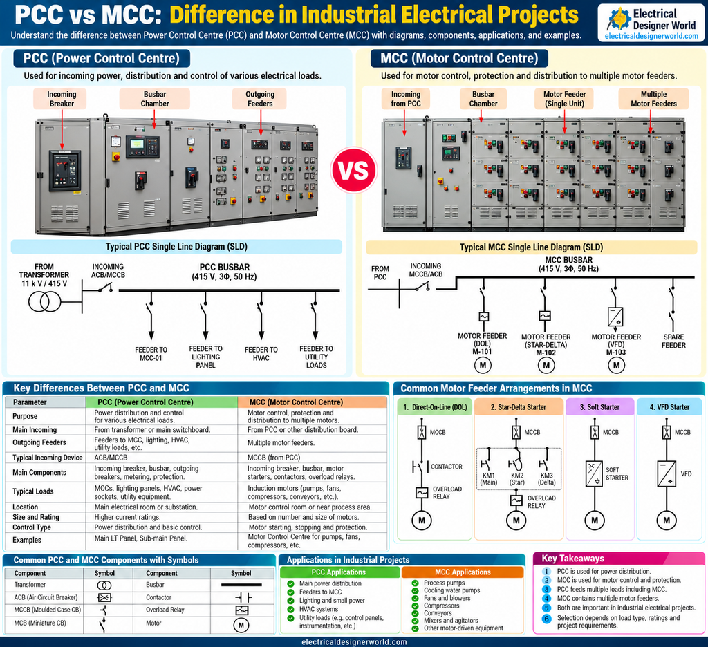
Table of Contents
PCC vs MCC is an important topic for electrical engineers and designers working on industrial Engineering, Procurement, and Construction (EPC) projects. Both Power Control Centres (PCCs) and Motor Control Centres (MCCs) are used in electrical distribution systems, but they serve different purposes.
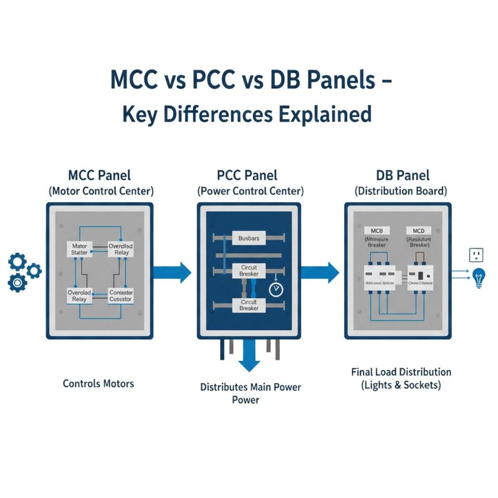
A PCC primarily distributes electrical power to downstream panels, MCCs, and other loads. An MCC primarily provides power distribution, switching, control, and protection for multiple motors.
Understanding the difference between PCC and MCC helps electrical designers read Single Line Diagrams (SLDs), identify electrical panels, understand motor feeder arrangements, and coordinate electrical design documents.
In this guide, we will compare PCC vs MCC, explain their components and applications, and show how they are represented in an industrial electrical SLD.
What Is a PCC (Power Control Centre)?
A Power Control Centre (PCC) is a low-voltage switchboard designed to receive and distribute electrical power to downstream distribution boards, MCCs, and other electrical loads.
In a typical industrial plant, the PCC receives power from a transformer secondary or another upstream source. It distributes this power through busbars and outgoing feeders to different sections of the electrical system.
Main functions of a PCC
- Receive electrical power from an upstream source.
- Distribute power to downstream MCCs and distribution panels.
- Provide switching and protection through appropriately selected devices.
- Measure electrical parameters such as current, voltage, and power.
- Support isolation and maintenance of electrical circuits.
- Distribute power to loads such as lighting panels, HVAC systems, and utility panels, where applicable.
Common PCC components
A typical PCC may include:
- Incoming Air Circuit Breaker (ACB) or another specified switching device.
- Main busbar system.
- Outgoing circuit breakers.
- Metering instruments.
- Protection relays where required.
- Control and indication devices.
- Busbar sections and coupling arrangements where specified.
The actual configuration depends on the plant load, voltage, fault level, redundancy requirements, and project specifications.
What Is an MCC (Motor Control Centre)?
A Motor Control Centre (MCC) is an electrical assembly used primarily to supply, control, and protect multiple motors in an industrial facility.
An MCC commonly receives power from a PCC or another suitable distribution source. It distributes this power through individual motor feeders connected to equipment such as pumps, fans, compressors, conveyors, and mixers.
Main functions of an MCC
- Distribute electrical power to individual motor feeders.
- Start and stop motors using suitable control arrangements.
- Provide motor switching and protection.
- Accommodate motor starters and drives where specified.
- Support local or remote motor control.
- Provide isolation and maintenance facilities according to the equipment design.
Common MCC components
An MCC may include:
- Incoming circuit breaker or switch.
- Main busbar system.
- Outgoing motor feeder compartments.
- Motor circuit breakers or fused protective devices.
- Contactors and overload relays.
- Direct-On-Line (DOL) starters.
- Star-delta starters.
- Soft starters.
- Variable Frequency Drives (VFDs).
- Control, indication, and communication equipment where specified.
Not every MCC contains all these components. The arrangement depends on the motor list, starting requirements, protection philosophy, and project specifications.
PCC vs MCC: Key Differences
The main difference between PCC and MCC is their primary function. A PCC focuses on power distribution, while an MCC focuses on supplying and controlling motor loads.
| Parameter | PCC — Power Control Centre | MCC — Motor Control Centre |
|---|---|---|
| Primary purpose | Power distribution | Motor power distribution, control, and protection |
| Typical incoming source | Transformer secondary or upstream switchboard | PCC or another approved distribution source |
| Typical outgoing feeders | MCCs, distribution boards, and other loads | Individual motor feeders |
| Main components | Incoming breaker, busbars, outgoing breakers, metering | Busbars, motor feeders, starters, contactors, motor protection |
| Typical loads | MCCs, lighting panels, HVAC panels, utility distribution | Pumps, fans, compressors, conveyors, mixers |
| Control functions | Primarily distribution and switching | Motor starting, stopping, and speed control where required |
| Motor starters | Not normally the primary function | Commonly provided in motor feeder compartments |
| Typical location | Electrical room or substation | Electrical room or near the process area, depending on design |
| Design considerations | Total load, fault level, feeder protection, distribution | Motor ratings, starting current, feeder protection, control requirements |
| Typical relationship | May supply one or more MCCs | May receive supply from a PCC |
Important: PCC and MCC are functional names. The actual equipment arrangement, ratings, and included functions must be verified against the project specification and approved electrical drawings.
PCC vs MCC in an Electrical Single Line Diagram (SLD)
Understanding the PCC and MCC arrangement is essential when reading an industrial electrical SLD.
A typical power distribution arrangement may look like this:
Transformer → PCC → MCC → Motor Loads
The transformer provides the electrical supply. The PCC distributes power to the MCC and other downstream loads. The MCC then supplies individual motor feeders.
Example of a typical PCC SLD
       11 kV / 415 V TRANSFORMER
                   |
            INCOMING BREAKER
                   |
              PCC BUSBAR
                   |
       +-----------+-----------+
       |           |           |
      MCC       LIGHTING      HVAC
    MCC-01       PANEL        PANEL
       |
       |  (MCC receives
       |   its own supply)
       v
    MOTOR FEEDERS
This simplified arrangement illustrates a possible distribution hierarchy. In practice, the PCC busbar may supply several separate loads, including one or more MCCs.
Example of a typical MCC SLD
             SUPPLY FROM PCC
                    |
               MCC INCOMER
                    |
                MCC BUSBAR
                    |
        +-----------+-----------+
        |           |           |
      FEEDER-1    FEEDER-2    FEEDER-3
        |           |           |
      STARTER     STARTER      VFD
        |           |           |
      MOTOR       MOTOR        MOTOR
       M-101       M-102        M-103
Each outgoing branch represents a separate motor feeder. Its protection and starter arrangement depend on the motor and the project design.
For a step-by-step guide to reading electrical drawings, see our Single Line Diagram (SLD) practical reading guide.
How PCC and MCC Work Together in an Industrial Plant
Consider an industrial plant containing several pumps, fans, lighting circuits, and utility loads.
The transformer supplies electrical power to the main distribution system. The PCC distributes that power to downstream panels and equipment. One outgoing PCC feeder may supply the MCC serving the process pumps, while other feeders supply lighting or HVAC distribution panels.
The MCC then distributes power to the individual pump motors through suitable motor feeders.
For example:
- PCC-01 supplies MCC-01.
- MCC-01 supplies pump motors P-101 and P-102.
- MCC-01 supplies fan motor F-101.
- PCC-01 supplies a separate lighting distribution panel.
- PCC-01 supplies an HVAC panel where required.
This arrangement makes it easier to understand the electrical distribution hierarchy and trace power from the source to individual equipment.
The actual system may include additional switchboards, transformers, bus couplers, standby supplies, or other arrangements based on the plant design.
Common Motor Feeder Arrangements in an MCC
The motor feeder arrangement depends on the motor rating, starting requirements, process needs, and protection philosophy.
1. Direct-On-Line (DOL) starter
A DOL starter connects the motor directly to the supply during starting.
It is commonly used where the motor and electrical system can accommodate the starting current and the application permits direct starting.
A conventional DOL starter may include a protective device, contactor, and overload relay.
2. Star-delta starter
A star-delta starter starts a suitably designed motor in a star connection and subsequently changes to a delta connection for normal operation.
It reduces starting current compared with DOL starting, but it also reduces starting torque. Motor suitability and load requirements must be checked.
3. Soft starter
A soft starter controls the applied motor voltage during starting to reduce starting stress and mechanical shock.
It is useful for applications where a controlled start and stop are required, subject to the equipment specification.
4. Variable Frequency Drive (VFD)
A VFD controls motor speed by varying the supply frequency and associated voltage.
It is commonly used for applications such as variable-flow pumps, fans, and process equipment that require speed control.
The use of a VFD introduces additional design considerations, including harmonics, cable requirements, motor compatibility, cooling, and electromagnetic compatibility where applicable.
PCC vs MCC: Which One Is Used for Different Loads?
The choice depends on the purpose of the equipment and the electrical distribution architecture.
| Application | Typical panel |
|---|---|
| Main distribution of plant electrical power | PCC or main switchboard |
| Distribution to multiple downstream panels | PCC |
| Supply to an MCC | PCC or another specified distribution board |
| Individual motor starting and protection | MCC |
| Pump motor control | MCC or dedicated motor control arrangement |
| Conveyor motor control | MCC or dedicated drive panel |
| Lighting distribution | Lighting distribution board, often supplied from a PCC |
| Variable-speed process motor | MCC with VFD compartments or a separate drive arrangement |
These are typical examples, not universal rules. A project’s electrical design basis and equipment specifications determine the actual arrangement.
Important Design Considerations for PCC and MCC Selection
Selecting PCC and MCC equipment requires more than identifying the panel name.
1. Load requirements
Determine the connected loads, demand, operating conditions, and future expansion requirements.
2. Voltage and current ratings
Verify the system voltage, busbar current rating, and feeder ratings against the approved design calculations.
3. Short-circuit rating
The switchboard or MCC assembly must be suitable for the prospective fault current and the applicable protection arrangement.
4. Protection coordination
Verify that incoming and outgoing protective devices are selected and coordinated according to the project’s protection philosophy.
5. Motor starting requirements
For an MCC, check the motor starting method, starting current, acceleration requirements, and any limitations on voltage dip.
6. Installation and environmental conditions
Consider indoor or outdoor installation, ambient temperature, enclosure protection, ventilation, access, and maintenance requirements.
7. Standards and project specifications
Verify the applicable IEC or other specified standards, manufacturer requirements, and project-specific technical specifications. Do not assume that every panel uses the same construction or protection arrangement.
For additional technical background on low-voltage electrical installations, consult Schneider Electric’s Electrical Installation Guide. For applicable international standards, visit the International Electrotechnical Commission (IEC).
Common Mistakes When Comparing PCC and MCC
1. Assuming a PCC cannot supply motors
A PCC can supply an MCC or other motor-related distribution equipment. The distinction is the primary function of the assembly, not whether motors ultimately receive power from it.
2. Assuming an MCC only contains contactors
An MCC may contain circuit breakers, fused devices, contactors, overload relays, soft starters, VFDs, and other equipment according to its design.
3. Assuming every MCC is supplied by a PCC
An MCC may receive power from a PCC, another switchboard, or another approved source. Follow the actual project SLD.
4. Confusing a panel name with its complete specification
The labels PCC and MCC do not define every electrical rating or internal arrangement. Always check the datasheet, approved drawings, and project specifications.
5. Ignoring the relationship between the SLD and motor list
The MCC feeder identification must be cross-checked against the motor list, equipment tags, cable schedule, and motor control drawings.
PCC vs MCC Review Checklist for EPC Electrical Designers
Use this checklist when reviewing industrial electrical distribution drawings.
- Identify the upstream power source.
- Confirm the PCC and MCC tags.
- Trace the incoming and outgoing feeders.
- Verify voltage, current, and short-circuit ratings.
- Identify the downstream loads supplied by the PCC.
- Identify the motor feeders supplied by the MCC.
- Verify the starter or VFD arrangement for each motor.
- Cross-check motor tags against the motor list.
- Cross-check cable identification against the cable schedule.
- Confirm that the latest approved drawings and specifications are used.
Frequently Asked Questions (FAQs)
1. What is the main difference between PCC and MCC?
A PCC primarily distributes electrical power to downstream panels and loads. An MCC primarily supplies, controls, and protects multiple motor feeders.
2. Can a PCC supply an MCC?
Yes. In a common industrial distribution arrangement, the PCC supplies an outgoing feeder to the MCC. The MCC then distributes power to individual motors.
3. Does an MCC have a circuit breaker?
Yes. An MCC may have an incoming circuit breaker and individual outgoing motor feeder protective devices. The actual arrangement depends on its design and specifications.
4. Is PCC used only for high-power loads?
No. A PCC is selected according to its distribution function, load requirements, and electrical ratings. It may supply several types of downstream equipment, including MCCs and other distribution panels.
5. Does every motor require an MCC?
No. A motor may be supplied from an MCC or through another suitable motor control and protection arrangement. The choice depends on the project design, motor requirements, and operating needs.
6. Which panel is shown first in an industrial electrical SLD, PCC or MCC?
In a common arrangement, the PCC appears upstream of the MCC: transformer, PCC, MCC, and motor loads. However, always follow the actual power distribution arrangement shown in the approved SLD.
7. What documents should an electrical designer check for PCC and MCC?
Review the electrical design basis, load list, SLD, switchboard or MCC datasheets, motor list, cable schedule, protection studies, and relevant equipment specifications.
Conclusion
Understanding PCC vs MCC helps electrical designers interpret industrial power distribution systems and identify the purpose of each electrical panel.
The PCC primarily distributes power to downstream panels and loads, while the MCC focuses on motor feeder distribution, switching, control, and protection.
In EPC projects, the next step is to trace the supply path in the SLD and cross-check panel tags, motor feeders, electrical ratings, and cable information against the approved project documents.
For more practical electrical design lessons, visit Electrical Designer World.