
Day 11: AC Waveform Explained – Amplitude, Frequency, Time Period and Phase
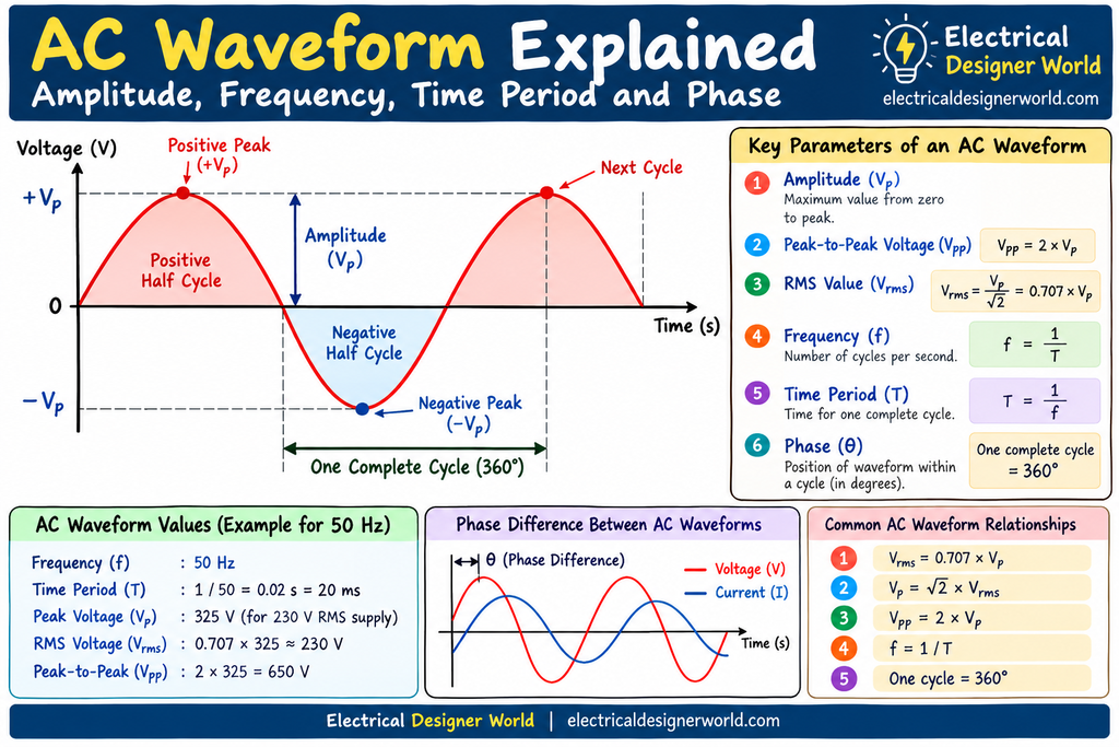
In this lesson of our 30 Day Electrical Fundamentals course, we will learn how to read an AC waveform, calculate frequency and time period, understand peak and RMS values, and identify phase differences between electrical signals.
An AC waveform is a graphical representation of how alternating voltage or current changes with time. Understanding AC waveforms is essential for learning electrical engineering because they help us understand voltage, current, frequency, power, and the behaviour of electrical equipment.
By the end of this lesson, you will be able to interpret a basic AC waveform and solve simple electrical calculations.
What Is an AC Waveform?
An AC waveform shows how alternating voltage or current changes continuously with time.
Unlike direct current (DC), which flows in one direction under normal steady-state conditions, alternating current (AC) periodically changes its magnitude and direction.
A common example is the sinusoidal voltage supplied by electrical generators and used in power systems.
An AC waveform normally has two axes:
- Vertical axis: Represents voltage or current.
- Horizontal axis: Represents time.
When the waveform is above the zero reference line, the instantaneous value is positive. When it is below the zero reference line, the instantaneous value is negative.
A complete cycle contains one positive alternation and one negative alternation.
Example of an AC Waveform
Imagine a voltage waveform that starts at zero, rises to a positive peak, returns to zero, falls to a negative peak, and finally returns to zero.
This complete pattern represents one cycle of a sinusoidal AC voltage.
Diagram suggestion: Add a labelled sine-wave diagram showing the positive peak, negative peak, zero crossing, amplitude, and one complete cycle.
Image ALT text: AC Waveform showing positive peak, negative peak, amplitude and one complete cycle.
Important Characteristics of an AC Waveform
An AC waveform has several important characteristics that help electrical engineers understand and analyse alternating electrical quantities.
The main characteristics are:
- Amplitude
- Peak voltage
- Peak-to-peak voltage
- Frequency
- Time period
- RMS value
- Average value
- Phase and phase difference
Let’s understand each characteristic with practical examples.
What Is Amplitude in an AC Waveform?
Amplitude is the maximum magnitude of a waveform measured from its zero reference level to its peak.
For a voltage waveform, amplitude is expressed in volts (V). For a current waveform, amplitude is expressed in amperes (A).
For example, if an AC voltage reaches a maximum positive value of 325 V and a minimum value of -325 V, its amplitude is 325 V.
Amplitude tells us how large the instantaneous voltage or current can become.
Peak Voltage and Peak-to-Peak Voltage
Peak voltage (Vp) is the maximum voltage measured from zero to the positive or negative peak for a symmetrical sine wave.
Peak-to-peak voltage (Vpp) is the difference between the positive and negative peak values.
For a symmetrical sine wave:
Vpp = 2 × Vp
Example:
If the peak voltage is 100 V:
Vpp = 2 × 100 = 200 V
Therefore, the peak-to-peak voltage is 200 V.
Remember that peak voltage and RMS voltage are different. Electrical supply voltages are commonly specified using their RMS values.
What Is Frequency in an AC Waveform?
Frequency is the number of complete cycles produced in one second.
It is measured in hertz (Hz).
The formula is:
Frequency (f) = Number of cycles / Time in seconds
For example, if an AC waveform completes 50 cycles in one second:
f = 50 / 1 = 50 Hz
This means the waveform completes 50 cycles every second.
In India, the standard mains electricity frequency is 50 Hz. This means the voltage waveform completes 50 cycles per second under normal operating conditions.
Frequency is important when studying transformers, motors, generators, switchgear, and electrical power systems.
What Is the Time Period of an AC Waveform?
The time period is the time required to complete one full cycle of a waveform.
It is represented by the symbol T and measured in seconds.
The relationship between frequency and time period is:
T = 1 / f
Where:
- T = Time period in seconds
- f = Frequency in hertz
AC Waveform Time Period Calculation
Consider a 50 Hz AC supply.
Given:
Frequency, f = 50 Hz
Formula:
T = 1 / f
Calculation:
T = 1 / 50
T = 0.02 seconds
Converting seconds into milliseconds:
T = 20 milliseconds
Therefore, a 50 Hz AC waveform completes one cycle in 20 milliseconds.
For a 60 Hz supply:
T = 1 / 60 = 0.01667 seconds
Therefore, the time period is approximately 16.67 milliseconds.
Important relationship: As frequency increases, the time period decreases.
What Is the RMS Value of an AC Waveform?
RMS stands for Root Mean Square.
The RMS value of an alternating voltage or current represents the equivalent DC value that would produce the same heating effect in a resistive load under the same conditions.
For a pure sinusoidal waveform:
Vrms = Vp / √2
Therefore:
Vrms ≈ 0.707 × Vp
For current:
Irms = Ip / √2
Therefore:
Irms ≈ 0.707 × Ip
RMS Voltage Calculation Example
Suppose the peak voltage of a sinusoidal waveform is 325 V.
Given:
Vp = 325 V
Formula:
Vrms = 0.707 × Vp
Calculation:
Vrms = 0.707 × 325
Vrms ≈ 229.8 V
Therefore, the RMS voltage is approximately 230 V.
This explains why a sinusoidal supply with a peak voltage of approximately 325 V has an RMS voltage of approximately 230 V.
Note: The 0.707 relationship applies to a pure sinusoidal waveform, not to every possible AC waveform.
What Is the Average Value of an AC Waveform?
The average value is calculated by adding the instantaneous values over a specified interval and dividing by the duration or number of equally spaced samples, as appropriate.
For a symmetrical sine wave, the average over one complete cycle is zero because the positive and negative halves cancel each other.
However, the average value over one positive half-cycle is:
Vavg = 2 × Vp / π
Approximately:
Vavg = 0.637 × Vp
Example:
If the peak voltage is 100 V:
Vavg = 0.637 × 100
Vavg = 63.7 V
Therefore, the average voltage over the positive half-cycle is approximately 63.7 V.
This distinction matters because average values depend on the interval over which they are calculated.
What Is Phase in an AC Waveform?
Phase describes the position of a waveform within its cycle relative to a reference point or another waveform.
Phase is usually measured in degrees or radians.
One complete cycle corresponds to 360 degrees.
Therefore:
- Half a cycle = 180°
- One-quarter of a cycle = 90°
- One-eighth of a cycle = 45°
Phase is especially important when comparing voltage and current in AC circuits.
Phase Difference Between Two AC Waveforms
When two waveforms have the same frequency but reach corresponding points at different times, they have a phase difference.
For example, if one waveform reaches its positive peak before another waveform, it is said to lead the other waveform.
The second waveform is said to lag the first.
In an ideal resistive AC circuit, voltage and current are in phase.
In an ideal inductive circuit, current lags voltage by 90°.
In an ideal capacitive circuit, current leads voltage by 90°.
These relationships are important for understanding power factor and AC circuit behaviour, which we will study in later lessons.
AC Waveform Formula Summary
The following formulas are useful when solving basic sinusoidal AC problems.
| Quantity | Formula |
|---|---|
| Frequency | f = 1 / T |
| Time period | T = 1 / f |
| Peak-to-peak voltage | Vpp = 2 × Vp |
| RMS voltage | Vrms = 0.707 × Vp |
| Peak voltage | Vp = √2 × Vrms |
| Average over positive half-cycle | Vavg = 0.637 × Vp |
| Phase of one complete cycle | 360° |
These RMS and average-value formulas assume a pure sinusoidal waveform, with the average-value formula referring to the positive half-cycle.
Practical Example: Analysing a 50 Hz AC Waveform
Suppose an electrical engineer is analysing a sinusoidal AC voltage with the following values:
- Frequency = 50 Hz
- Peak voltage = 325 V
Calculate the time period, RMS voltage, and peak-to-peak voltage.
Step 1: Calculate the time period
T = 1 / f
T = 1 / 50 = 0.02 seconds
Time period = 20 milliseconds.
Step 2: Calculate the RMS voltage
Vrms = 0.707 × 325
Vrms ≈ 230 V.
Step 3: Calculate the peak-to-peak voltage
Vpp = 2 × 325
Vpp = 650 V.
Final answers:
- Time period = 20 ms
- RMS voltage ≈ 230 V
- Peak-to-peak voltage = 650 V
These calculations help connect waveform characteristics with the electrical quantities used in practical power systems.
Why Is Understanding an AC Waveform Important?
Understanding AC waveforms provides the foundation for more advanced electrical engineering concepts.
It helps you understand:
- How alternating voltage and current change with time.
- The relationship between frequency and time period.
- The difference between peak and RMS voltage.
- How voltage and current can lead or lag each other.
- The fundamentals of inductive and capacitive circuits.
- The concepts behind power factor and AC power calculations.
- How sinusoidal signals are represented in electrical measurements.
For electrical engineering students and professionals, these fundamentals are useful before studying transformers, motors, protection systems, and power distribution.
Practice Questions: AC Waveform
Test your understanding by answering the following questions.
Question 1: What does the frequency of an AC waveform represent?
A. Maximum voltage
B. Number of cycles per second
C. Time required for half a cycle
D. Resistance of the circuit
Question 2: What is the time period of a 50 Hz AC waveform?
A. 5 ms
B. 10 ms
C. 20 ms
D. 50 ms
Question 3: If the peak voltage is 100 V, what is its RMS value for a pure sine wave?
A. 50 V
B. 70.7 V
C. 100 V
D. 141.4 V
Question 4: What is the phase angle corresponding to one complete cycle?
A. 90°
B. 180°
C. 270°
D. 360°
Question 5: What is the average value of a symmetrical sine wave over one complete cycle?
A. Zero
B. 0.5 times peak value
C. 0.707 times peak value
D. Equal to peak value
Answers
- B — Number of cycles per second.
- C — 20 ms.
- B — Approximately 70.7 V.
- D — 360°.
- A — Zero.
Frequently Asked Questions About AC Waveforms
1. What is an AC waveform?
An AC waveform is a graphical representation of how alternating voltage or current varies with time.
2. What is the difference between frequency and time period?
Frequency is the number of cycles per second, measured in hertz. Time period is the time taken to complete one cycle, measured in seconds. They are reciprocals of each other.
3. Why is RMS voltage used in electrical systems?
RMS voltage provides an effective value that can be used to calculate the heating effect of an AC voltage across a resistor.
4. What is the difference between peak voltage and RMS voltage?
Peak voltage is the maximum instantaneous voltage of a waveform. RMS voltage represents its effective value. For a pure sine wave, RMS voltage is approximately 0.707 times the peak voltage.
5. What does phase difference mean?
Phase difference describes the angular displacement between two periodic waveforms of the same frequency. It indicates whether one waveform leads or lags the other.
Conclusion
An AC waveform helps us understand how alternating voltage and current change with time. Its important characteristics include amplitude, peak voltage, frequency, time period, RMS value, average value, and phase.
By learning these concepts and practising the calculations, you can build a strong foundation for studying AC circuits, electrical machines, power factor, and electrical power systems.
Continue practising the formulas and interpreting waveform diagrams before moving to the next lesson.
Continue the 30 Day Electrical Fundamentals Course
This lesson is part of the Electrical Fundamentals – Zero to Advanced course on Electrical Designer World.
- Previous lesson: Day 10 – AC and DC Fundamentals
- Current lesson: Day 11 – AC Waveforms
- Next lesson: Day 12 – Continue to the next topic in the course sequence.
Explore related lessons on voltage, current, frequency, and electrical circuits on Electrical Designer World.
for reference: All About Circuits – Textbook, for further reading on AC circuit fundamentals.