
AC and DC Electricity: Understanding Alternating and Direct Current
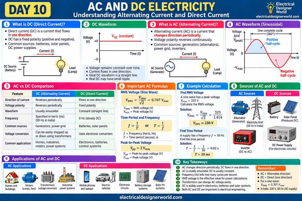
Table of Contents
Introduction
Electricity powers our homes, offices, industries, computers, mobile phones, and electrical equipment. But did you know that electricity can flow in two different ways?
These two types are called AC (Alternating Current) and DC (Direct Current).
The electricity supplied to homes in India is AC, while a typical battery supplies DC. Both are important in electrical engineering, but they behave differently and are used for different purposes.
Understanding AC and DC electricity is essential for learning electrical engineering. AC and DC electricity are used in different applications, from household power distribution to batteries, solar systems, and electronic equipment.
In Day 9, we learned about electromagnetic induction, where a changing magnetic flux can produce voltage. In Day 10, we will learn about AC and DC, understand their waveforms, compare their characteristics, and explore where they are used in real electrical systems.
By the end of this lesson, you should be able to explain AC and DC in simple words, identify their waveforms, understand frequency and peak voltage, and solve a basic AC voltage calculation.
1. What Is Electric Current?
Before learning AC and DC, let us understand electric current.
Electric current is the rate at which electric charge flows through a conductor.
For example, when you connect a battery to a small lamp using wires, electric current flows through the circuit and the lamp lights up.
The formula for electric current is:
Where:
- (I) = electric current, measured in amperes (A)
- (Q) = electric charge, measured in coulombs (C)
- (t) = time, measured in seconds (s)
Simple example
Suppose 10 coulombs of charge pass through a conductor in 2 seconds.
Answer: The average current is 5 amperes.
Electric current is measured in amperes using an instrument called an ammeter.
Now let us understand the two main types of current.
2. What Is DC (Direct Current)?
Direct current (DC) is electric current that flows in one direction through a circuit.
A common example is the current supplied by a battery to a simple DC circuit.
Imagine connecting a battery to a torch. The battery provides a voltage with fixed polarity, and conventional current flows through the external circuit from the positive terminal towards the negative terminal.
In a simple battery-powered circuit, the current flows in one direction while the battery maintains its polarity. The actual current and voltage may change over time as the battery discharges or the circuit conditions change.
Common sources of DC
- Batteries
- Solar panels (which produce DC)
- USB power supplies, after conversion and regulation
- DC power supplies used in electronic equipment
- Battery storage systems
Where is DC used?
DC is widely used in mobile phones, laptops, electronic circuits, battery-powered tools, control circuits, and many industrial systems.
For example, a mobile phone battery supplies DC to the phone’s internal electronic circuits. A charger converts the available AC supply into suitable DC for charging the battery.
Important points about DC
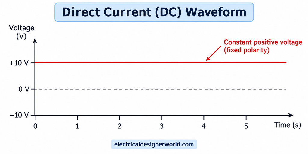
- Current flows in one direction.
- Voltage polarity remains the same for a normal DC source.
- An ideal constant DC source has a steady voltage.
- Real DC sources may have voltage ripple or change as their energy source changes.
- Batteries and solar panels are common DC sources.
Remember: DC does not always mean that the voltage must be perfectly constant. The defining feature is its direction and polarity in the usual circuit context.
3. What Is AC (Alternating Current)?
Alternating current (AC) is electric current that changes direction periodically.
Unlike a typical battery, which maintains fixed polarity, an AC source reverses its voltage polarity repeatedly. In a resistive circuit, the current reverses direction along with the voltage.
The electricity supplied to homes in India is AC. The standard supply frequency is 50 hertz (Hz).
How does AC work?
Imagine a coil rotating inside a magnetic field. As the coil rotates, the magnetic flux linking it changes. This produces an induced voltage.
As the coil continues rotating, the induced voltage changes magnitude and reverses polarity periodically. This produces an alternating voltage. When the circuit is connected to a load, alternating current can flow.
This is the basic principle behind an AC generator.
Common sources of AC
- Alternators and electrical generators
- Power stations and the electricity grid
- Inverters, which convert DC into AC
- AC generators used in industrial and backup power systems
Where is AC used?
AC is used in homes, commercial buildings, factories, and electrical distribution systems. It supplies equipment such as fans, pumps, air conditioners, and many industrial machines.
Important points about AC
- Current reverses direction periodically in a typical AC circuit.
- Voltage polarity also reverses periodically.
- AC can be described by frequency, time period, peak value, and RMS value.
- A sinusoidal AC waveform is common in power systems.
- AC voltage can be increased or decreased using transformers.
4. AC and DC Electricity: Key Differences?
The main difference is how voltage polarity and current direction behave over time.
The main difference between AC and DC electricity is the direction of current flow. AC reverses direction periodically, while DC flows in one direction in a typical circuit. Understanding this difference helps engineers select suitable equipment and power supplies.
| Feature | AC (Alternating Current) | DC (Direct Current) |
|---|---|---|
| Direction | Reverses periodically in a typical AC circuit | Flows in one direction |
| Voltage polarity | Reverses periodically | Normally remains fixed |
| Waveform | Often sinusoidal in power systems | Often steady, but may contain ripple |
| Frequency | Usually specified in hertz | Steady DC has 0 Hz; changing DC waveforms need more careful description |
| Common source | Alternators and the power grid | Batteries and solar panels |
| Voltage conversion | Transformers can change AC voltage | Electronic converters are commonly used to change DC voltage |
| Common applications | Household supply, motors, industrial power | Batteries, electronics, control systems, DC drives |
Simple way to remember
- AC: Alternates direction.
- DC: Maintains one direction.
Neither type is universally better. The right choice depends on the source, load, transmission system, and application.
5. What Is an AC Waveform?
A waveform is a graph that shows how voltage or current changes with time.
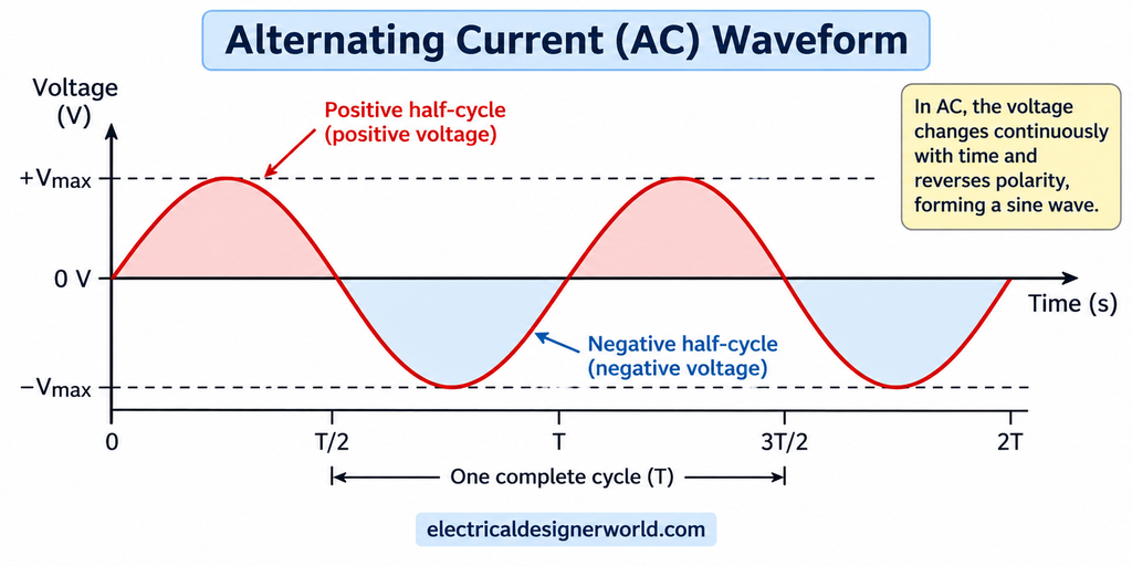
A sinusoidal AC waveform rises from zero to a positive peak, falls through zero, reaches a negative peak, and returns to zero. This pattern repeats during each cycle.
A typical AC waveform has several important characteristics.
5.1 Positive half-cycle
During the positive half-cycle, the instantaneous voltage is positive relative to the chosen reference direction.
5.2 Negative half-cycle
During the negative half-cycle, the voltage polarity is reversed relative to that reference.
5.3 One complete cycle
One complete cycle includes one positive half-cycle and one negative half-cycle for a standard sine wave.
5.4 Peak voltage
Peak voltage is the maximum instantaneous voltage measured from zero to the positive or negative peak.
It is represented by (V_{\text{max}}) or (V_p).
5.5 Peak-to-peak voltage
Peak-to-peak voltage is the difference between the positive peak and negative peak.
For a symmetrical sine wave:
For example, if the positive peak is +10 V and the negative peak is −10 V:
Vpp = 10 − (−10) = 20 V
Explanation: Peak-to-peak voltage is the difference between the maximum positive voltage and the maximum negative voltage.
Peak voltage = +10 V Minimum voltage = −10 V
Therefore, Vpp = 10 + 10 = 20 V
6. What Is Frequency in AC Electricity?
Frequency tells us how many complete cycles occur in one second.
It is measured in hertz (Hz).
f = 1 ÷ T
Where:
- f = Frequency in hertz (Hz)
- T = Time period in seconds (s)
Example: If the time period is 0.02 seconds:
f = 1 ÷ 0.02 = 50 Hz
Worked example: Calculate the time period
An AC supply has a frequency of 50 Hz. Find the time period.
Step 1: Write the formula
T = 1 ÷ f
Step 2: Substitute the frequency
T = 1 ÷ 50 = 0.02 seconds
Step 3: Convert seconds to milliseconds
0.02 × 1,000 = 20 milliseconds (ms)
Answer: One complete AC cycle takes 20 milliseconds at a frequency of 50 Hz.
This is why frequency is important when studying AC systems. It tells us how quickly the waveform repeats.
7. What Is RMS Voltage?
RMS stands for Root Mean Square.
RMS voltage is an effective value used to compare AC voltage with DC voltage in terms of heating effect in a resistor.
For a pure sinusoidal AC voltage:
RMS Voltage Formula
RMS voltage is calculated using:
VRMS = Vp ÷ √2
Since √2 ≈ 1.414:
VRMS ≈ 0.707 × Vp
Where:
- VRMS = Root mean square voltage
- Vp = Peak voltage
Example calculation:
If the peak voltage is 325 V:
VRMS = 325 ÷ 1.414
VRMS ≈ 230 V
Answer: The RMS voltage is approximately 230 V.
This relationship applies to a sinusoidal waveform, not every possible AC waveform.
Worked example: Calculate RMS voltage
Suppose an AC sine wave has a peak voltage of 325 V. Calculate its RMS voltage.
Step 1: Write the formula
VRMS = Vp ÷ √2
Step 2: Substitute the peak voltage
VRMS = 325 ÷ 1.414
Step 3: Calculate the RMS voltage
VRMS ≈ 229.8 V
Answer: The RMS voltage is approximately 230 V.
This is close to the nominal 230 V single-phase supply used in India. The example illustrates the relationship between peak and RMS voltage; actual supply voltage varies within permitted limits.
Why is RMS important?
Electrical supply voltage ratings are generally expressed as RMS values for AC systems. RMS values are useful for calculations involving power, current, and equipment ratings.
For a pure sinusoidal waveform across a resistor:
P = VRMS² ÷ R
Where:
- P = Electrical power in watts (W)
- VRMS = RMS voltage in volts (V)
- R = Resistance in ohms (Ω)
Example: If VRMS = 230 V and R = 46 Ω:
P = 230² ÷ 46 = 1,150 W
8.AC and DC Electricity in Power Distribution?
AC is widely used for electrical power distribution because its voltage can be changed efficiently using transformers.
Suppose electrical power must be transmitted over a long distance. For a given amount of power, increasing the transmission voltage reduces the current required.
The relationship between power, voltage, and current in a simple DC circuit or a single-phase resistive load is:
Electrical Power Formula
P = V × I
Where:
- P = Electrical power in watts (W)
- V = Voltage in volts (V)
- I = Current in amperes (A)
Current Formula for Fixed Power
I = P ÷ V
For a fixed power, if voltage increases, the required current decreases.
Power Loss in a Transmission Conductor
P_loss = I² × R
Where:
- P_loss = Power lost as heat in watts (W)
- I = Current in amperes (A)
- R = Conductor resistance in ohms (Ω)
Key point: Higher current causes greater power loss in the conductor. Since power loss is proportional to the square of the current, doubling the current increases the loss by four times
In AC power systems, transformers step voltage up for transmission and step it down for distribution and use. This is one major reason AC became widely used in conventional electrical grids.
Modern HVDC systems also transmit power efficiently over certain long-distance and subsea routes, so AC is not always the best option for every transmission application.
9. Can AC Be Converted into DC?
Yes. A device called a rectifier converts AC into DC.
A typical power supply may contain these stages:
- Transformer or input stage: Adjusts voltage when required.
- Rectifier: Converts AC into pulsating DC.
- Filter: Reduces voltage ripple.
- Regulator: Helps maintain the required DC output.
For example, a mobile phone charger receives AC from the mains and converts it into a suitable DC output for the phone or battery.
A DC-to-DC converter can also change one DC voltage level to another. An inverter does the opposite type of conversion: it converts DC into AC.
10. Practical Applications of AC and DC
AC applications
- Household and commercial power supply
- Industrial pumps and fans
- Air conditioners and other appliances
- Power transmission and distribution
- AC motors and transformers
DC applications
- Mobile phones and computers
- Battery storage and electric vehicles
- Solar photovoltaic systems
- Electronic control circuits
- DC motors and industrial DC drives
- Battery-backed control and emergency systems
In real installations, AC and DC often work together. For example, a solar installation produces DC at the panels, uses power electronics to convert energy as required, and may supply AC to a building or the grid.
11. Common Beginner Mistakes
Mistake 1: Thinking AC and DC differ only in voltage.
Their defining difference is the behaviour of current direction and voltage polarity over time.
Mistake 2: Thinking DC must always be perfectly constant.
DC can vary in magnitude while maintaining the same polarity and direction.
Mistake 3: Confusing peak voltage with RMS voltage.
For a sine wave, RMS voltage is approximately 70.7% of peak voltage.
Mistake 4: Thinking a transformer normally works from steady DC.
A conventional transformer relies on changing magnetic flux, which is normally produced by AC in its primary winding.
Mistake 5: Thinking all AC waveforms are sine waves.
AC can have other wave shapes, including square and triangular waveforms. The familiar sine wave is common in electrical power systems.
12. Practice Questions
Try answering these questions before checking your understanding.
- What is electric current?
- What does DC stand for?
- What does AC stand for?
- What is the standard frequency of mains electricity in India?
- What is the difference between peak voltage and RMS voltage?
- Why are transformers important in AC power distribution?
- Which device converts AC into DC?
- An AC sine wave has a peak voltage of 100 V. Calculate its RMS voltage.
- Calculate the time period of a 25 Hz AC waveform.
Answers
- Electric current is the rate of flow of electric charge.
- Direct Current.
- Alternating Current.
- 50 Hz.
- Peak voltage is the maximum instantaneous value; RMS voltage is the effective value for power calculations.
- Transformers allow AC voltage to be increased or decreased efficiently.
- A rectifier.
- (V_{\text{RMS}}=100/\sqrt{2}\approx70.7\text{ V}).
- (T=1/25=0.04\text{ s}=40\text{ ms}).
13. Frequently Asked Questions
Is household electricity AC or DC in India?
Household mains electricity in India is AC, nominally 230 V single-phase at 50 Hz.
Are batteries AC or DC?
Typical batteries supply DC, with fixed terminal polarity during normal operation.
Why do mobile phones use DC?
Their electronic circuits and batteries operate on DC. A charger converts the AC mains supply into suitable DC.
What is the difference between frequency and time period?
Frequency is the number of complete cycles per second. Time period is the time taken for one complete cycle.
Can DC be converted into AC?
Yes. An inverter converts DC into AC.
Which is safer, AC or DC?
Neither should be assumed safe. The danger depends on voltage, current, exposure time, current path through the body, and other conditions. Both AC and DC can cause serious injury or death.
Conclusion
AC and DC are two essential forms of electricity. AC reverses direction periodically, while DC maintains one direction in a typical circuit. AC is widely used in electrical distribution because transformers can change its voltage efficiently, while DC is essential for batteries, electronics, solar systems, and many control applications.
Understanding current, waveforms, frequency, peak voltage, and RMS voltage provides a strong foundation for the next electrical engineering topics.
Next lesson — Day 11: Voltage, Current, Resistance, and Ohm’s Law. We will connect these basic quantities and learn how to calculate voltage, current, and resistance in simple electrical circuits.
References for Further Learning
- OpenStax, University Physics Volume 2: https://openstax.org/details/books/university-physics-volume-2
- OpenStax, College Physics 2e: https://openstax.org/details/books/college-physics-2e
For more beginner-friendly electrical engineering lessons, visit Electrical Designer World.