
Electrical Faults – Types, Causes, Effects and Protection
Table of Contents
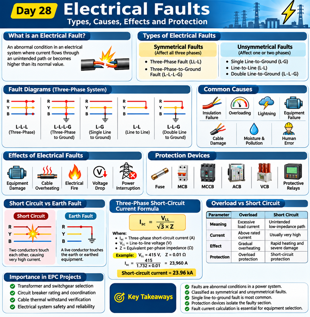
Introduction
An electrical fault is an abnormal condition in an electrical system where current flows through an unintended path or becomes higher than its normal value.
In simple words, an electrical fault happens when something goes wrong in an electrical circuit.
For example, when two electrical wires accidentally touch each other, a short circuit can occur. This may produce very high current and damage electrical equipment.
Electrical faults can affect cables, transformers, motors, generators and switchgear.
Understanding different types of electrical faults helps electrical engineers design safe and reliable electrical systems.
1. What Are Electrical Faults?
Under normal conditions, electrical current flows through the intended path in a circuit.
However, when insulation fails, conductors touch each other, or a conductor comes into contact with the ground, an abnormal condition occurs. This is called an electrical fault.
Example:
Imagine a cable supplying power to an electric motor. If the cable insulation becomes damaged and two conductors touch each other, a short-circuit fault can occur.
The fault current may increase suddenly, causing the circuit breaker to trip and disconnect the faulty circuit.
2. Types of Electrical Faults
Electrical faults in three-phase power systems are mainly classified into two categories:
- Symmetrical faults
- Unsymmetrical faults
A. Symmetrical Faults
A symmetrical fault occurs when all three phases are affected equally.
There are two common types.
1. Three-Phase Fault (L-L-L)
All three phase conductors come into contact with each other.
2. Three-Phase-to-Ground Fault (L-L-L-G)
All three phase conductors come into contact with the ground.
Characteristics of symmetrical faults:
- All three phases are affected equally.
- The fault condition remains balanced.
- Very high fault current can occur.
- These faults are important when calculating maximum short-circuit current.
B. Unsymmetrical Faults
An unsymmetrical fault affects one or two phases of a three-phase electrical system.
There are three common types.
1. Single Line-to-Ground Fault (L-G)
One phase conductor comes into contact with the ground.
Example: A damaged phase cable touches an earthed metal surface.
2. Line-to-Line Fault (L-L)
Two phase conductors come into contact with each other.
Example: Two damaged phase cables accidentally touch each other.
3. Double Line-to-Ground Fault (L-L-G)
Two phase conductors come into contact with the ground.
These faults create an unbalanced condition in the electrical system.
3. Common Causes of Electrical Faults
Electrical faults can occur due to several reasons.
1. Insulation Failure
Damaged or aged insulation allows unwanted contact between conductors.
2. Overloading
When electrical equipment operates above its rated capacity, excessive current can cause overheating.
3. Lightning
Lightning can introduce high-voltage surges into electrical systems.
4. Equipment Failure
Transformers, motors, generators and switchgear can develop internal faults.
5. Cable Damage
Physical damage during installation or maintenance can expose electrical conductors.
6. Moisture and Pollution
Water, dust, chemicals and corrosion can reduce insulation performance.
7. Human Error
Incorrect wiring, improper connections and maintenance mistakes can create electrical faults.
4. Effects of Electrical Faults
Electrical faults can cause serious damage if they are not detected and isolated quickly.
Common effects include:
- Equipment damage.
- Cable overheating.
- Electrical fires.
- Voltage drops.
- Power supply interruptions.
- Transformer and motor damage.
- Electric shock hazards.
- Instability in the power system.
For example, a short circuit in an electrical distribution panel can produce extremely high current and damage the connected equipment.
5. Electrical Fault Protection Devices
Electrical protection devices detect abnormal conditions and help disconnect the faulty part of the electrical system.
Common protection devices include:
1. Fuse
A fuse melts when excessive current flows through it, disconnecting the circuit.
2. MCB (Miniature Circuit Breaker)
An MCB protects electrical circuits against overload and short circuits.
3. MCCB (Moulded Case Circuit Breaker)
An MCCB provides protection for higher-current electrical distribution circuits.
4. ACB (Air Circuit Breaker)
An ACB is commonly used in low-voltage main distribution systems.
5. VCB (Vacuum Circuit Breaker)
A VCB interrupts fault current in medium-voltage electrical systems.
6. Overcurrent Relay
It detects current above a preset value and sends a trip signal to the circuit breaker.
7. Earth Fault Relay
It detects earth fault conditions and initiates protective action.
8. Differential Relay
It compares the current entering and leaving protected equipment to detect internal faults.
6. What Is a Short-Circuit Fault?
A short circuit occurs when two conductors at different electrical potentials come into contact through a low-impedance path.
This causes a sudden increase in current.
Example:
Consider a 415 V three-phase electrical system.
If two phase conductors accidentally touch each other, a large fault current may flow through the circuit.
The protective circuit breaker detects the fault and interrupts the current.
Short circuits can damage cables, switchgear and electrical equipment if the fault is not cleared quickly.
7. What Is an Earth Fault?
An earth fault occurs when a live electrical conductor unintentionally comes into contact with the earth or an earthed metallic part of equipment.
Example:
Imagine a motor connected to a three-phase electrical supply.
If the motor cable insulation becomes damaged and a phase conductor touches the motor body, an earth fault can occur.
An appropriate earth fault protection system detects the abnormal condition and helps isolate the faulty circuit.
8. What Is Fault Current?
Fault current is the current that flows through an electrical system during a fault condition.
It is generally much higher than normal operating current, depending on the type and location of the fault.
Fault current depends on:
- System voltage.
- Transformer impedance.
- Source impedance.
- Cable impedance.
- Fault location.
- Fault impedance.
Three-Phase Short-Circuit Current Formula
The basic formula for calculating three-phase short-circuit current is:
Isc = VLL / (√3 × Z)
Where:
- Isc = Three-phase short-circuit current (A).
- VLL = Line-to-line voltage (V).
- Z = Equivalent per-phase impedance (Ω).
Example Calculation
Given:
- System voltage = 415 V.
- Equivalent impedance = 0.01 Ω.
Step 1: Write the formula
Isc = VLL / (√3 × Z)
Step 2: Substitute the values
Isc = 415 / (1.732 × 0.01)
Step 3: Calculate
Isc = 415 / 0.01732
Isc = 23,960 A
Final Answer:
Short-circuit current = 23.96 kA
Note: This formula assumes a balanced three-phase fault and uses the equivalent per-phase Thevenin impedance at the fault location.
9. Importance of Fault Analysis in EPC Projects
Fault analysis is an important activity in Engineering, Procurement and Construction (EPC) electrical projects.
Electrical engineers perform short-circuit calculations to determine the maximum fault current at different points in an electrical distribution system.
These calculations help engineers select equipment with suitable ratings.
Fault analysis is important for:
- Transformer selection.
- Circuit breaker selection.
- Switchgear rating verification.
- Cable thermal withstand verification.
- Protection relay coordination.
- Electrical system safety.
- Short-circuit study reports.
Practical EPC Example:
Suppose the calculated short-circuit current at a switchboard is 35 kA.
The selected switchgear and circuit breakers must have suitable short-circuit withstand and breaking capacities for the calculated fault level.
This helps prevent equipment damage and improves electrical system safety.
10. Difference Between Overload and Short Circuit
These two conditions are different, although both can cause excessive current.
| Parameter | Overload | Short Circuit |
|---|---|---|
| Meaning | Excessive load current | Unintended low-impedance connection |
| Current | Above rated current | Usually very high |
| Cause | Excessive connected load | Insulation failure or conductor contact |
| Effect | Gradual overheating | Rapid heating and severe damage |
| Protection | Overload protection | Short-circuit protection |
Simple explanation:
Overload happens when equipment carries more current than its rated capacity.
Short circuit happens when current flows through an unintended low-impedance path.
11. Key Takeaways
- Electrical faults are abnormal conditions in an electrical system.
- Faults are classified as symmetrical and unsymmetrical.
- Single line-to-ground faults are common in power systems.
- Three-phase faults can produce very high fault currents.
- Short circuits and earth faults require suitable protection.
- Circuit breakers and protective relays help isolate faulty sections.
- Fault current calculations are essential for electrical equipment selection.
- Fault analysis improves electrical system safety and reliability.
12. Frequently Asked Questions (FAQs)
1. What is an electrical fault?
An electrical fault is an abnormal condition in which current flows through an unintended path or the electrical system operates outside normal limits.
2. What is the most common electrical fault?
The single line-to-ground fault is generally the most common fault in electrical power systems.
3. What is the most severe electrical fault?
A three-phase short-circuit fault is generally considered the most severe in terms of fault current.
4. What is the difference between symmetrical and unsymmetrical faults?
Symmetrical faults affect all three phases equally, whereas unsymmetrical faults affect one or two phases.
5. Which device protects against short circuits?
Fuses, MCBs, MCCBs and circuit breakers provide short-circuit protection, depending on the application.
6. What is the purpose of an earth fault relay?
An earth fault relay detects earth fault conditions and initiates a trip signal to isolate the faulty circuit.
7. Why is fault current calculation important?
It helps electrical engineers select suitable circuit breakers, switchgear, cables and protective devices.
Related Articles
Continue learning with our Electrical Fundamentals – Zero to Advanced Course.
To understand three-phase electrical systems, read our guide on Three-Phase Power Calculations.
External References
For more technical information about electrical power system faults, explore these resources:
- IEEE – Power System Engineering
- OSHA – Electrical Safety Guidelines
- Electrical Engineering Portal – Power System Protection
Conclusion
Electrical faults are an important subject in electrical engineering because they directly affect the safety and reliability of electrical systems.
Understanding different fault types, their causes, effects and protection methods helps electrical engineers design better electrical installations.
Proper fault analysis and protection coordination are essential for preventing equipment damage and maintaining a reliable power supply.
In the next lesson, we will learn about Electrical Protection Systems and how protective relays and circuit breakers work together to protect electrical equipment.