
Electrical Transients – Causes, Types, Effects and Protection Methods
Table of Contents
Introduction
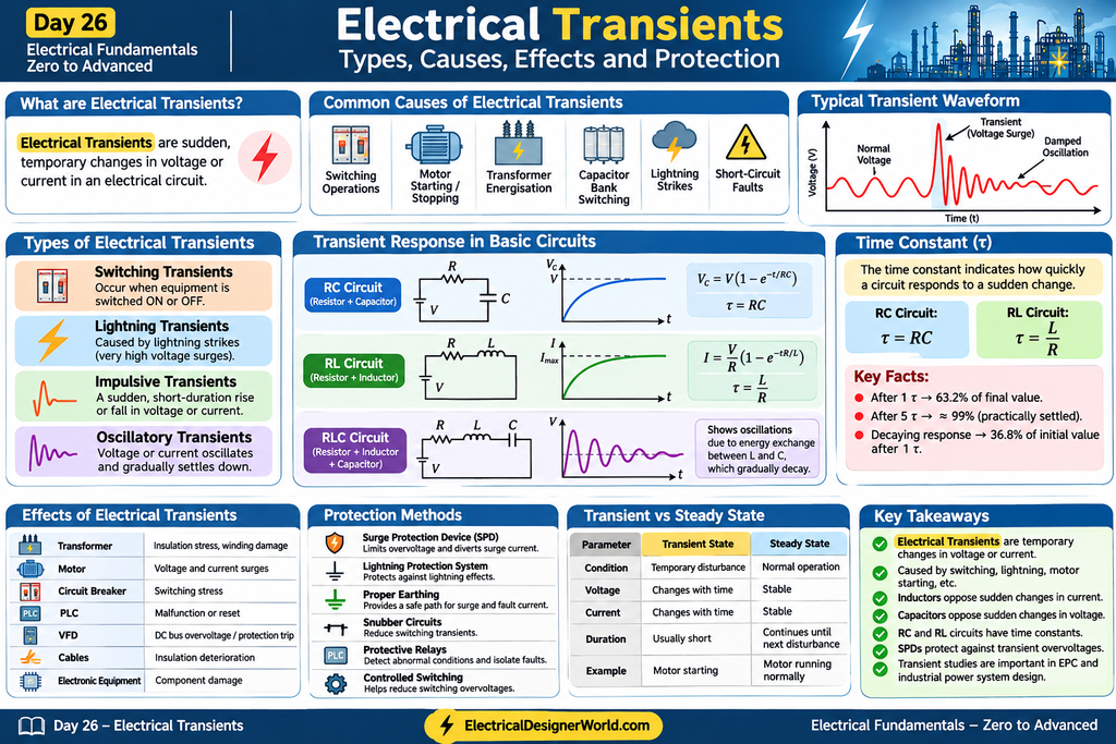
Electrical transients are sudden, temporary changes in voltage or current in an electrical circuit. These disturbances usually occur when an electrical system experiences a sudden change in operating conditions, such as switching operations, lightning strikes, motor starting, or short circuits.
Electrical transients can cause serious problems in industrial electrical systems, including equipment damage, insulation failure, protection relay operation, and malfunctioning of sensitive electronic devices.
Understanding electrical transients is essential for electrical engineers involved in power system design, electrical protection, substations, and EPC projects.
In this lesson, we will understand the meaning, causes, types, effects, calculations, and protection methods of electrical transients.
1. What Are Electrical Transients?
Electrical transients are short-duration disturbances that cause sudden changes in voltage or current before the electrical system returns to a stable operating condition.
For example, consider an electrical system operating normally at 230 V. When a switching operation occurs, the voltage may suddenly increase or decrease for a very short period.
This temporary disturbance is called an electrical transient.
Electrical transients can occur in both AC and DC electrical systems.
Common examples include:
- Switching ON or OFF a circuit breaker.
- Transformer energisation.
- Motor starting and stopping.
- Lightning strikes.
- Capacitor bank switching.
- Sudden load changes.
- Short-circuit faults.
2. Causes of Electrical Transients
Electrical transients can occur due to several reasons.
2.1 Switching Operations
Switching operations are one of the common causes of electrical transients.
When circuit breakers, contactors, or isolating devices operate, sudden changes in circuit conditions can produce temporary voltage and current disturbances.
Examples:
- Transformer switching.
- Circuit breaker opening and closing.
- Capacitor bank switching.
- Motor switching.
2.2 Lightning Strikes
Lightning can introduce extremely high transient voltages into electrical installations.
These surges may enter through overhead transmission lines, distribution lines, or nearby electrical structures.
Lightning transients can damage:
- Transformers.
- Switchgear.
- Insulation systems.
- Electronic equipment.
- Control and instrumentation systems.
2.3 Motor Starting
When an induction motor starts, it generally draws a high starting current compared with its normal running current.
This sudden current demand can cause temporary voltage dips in the electrical system.
2.4 Short-Circuit Faults
Short-circuit faults produce sudden and significant changes in current and voltage.
These disturbances can create electromagnetic and switching transients during fault occurrence and circuit breaker operation.
3. Types of Electrical Transients
Electrical transients are commonly classified according to their waveform and characteristics.
3.1 Switching Transients
Switching transients occur when electrical equipment is switched ON or OFF.
Examples include:
- Transformer energisation.
- Capacitor bank switching.
- Circuit breaker operations.
- Motor switching.
These operations can produce temporary overvoltages or oscillations in the electrical system.
3.2 Lightning Transients
Lightning transients occur due to lightning strikes that introduce high-voltage surges into electrical networks.
They are particularly dangerous for overhead transmission lines, substations, and outdoor electrical installations.
3.3 Impulsive Transients
An impulsive transient is a sudden, short-duration change in voltage or current that moves in one direction from its normal value.
It generally has a rapid rise followed by a decay.
Lightning-induced surges are a common example of impulsive transients.
3.4 Oscillatory Transients
Oscillatory transients involve voltage or current variations that move above and below their normal values.
They gradually decrease in magnitude due to resistance and energy losses in the circuit.
They commonly occur in electrical systems containing inductance and capacitance.
4. Transient Response in Electrical Circuits
To understand transient behaviour, we need to study three basic electrical circuits.
4.1 RC Circuit (Resistor and Capacitor)
An RC circuit consists of a resistor and capacitor connected together.
When a DC supply is connected, the capacitor does not charge instantaneously. Instead, its voltage increases gradually.
The capacitor charging equation is:
Vc = V(1 – e^(-t/RC))
Where:
- Vc = Capacitor voltage in volts.
- V = Supply voltage in volts.
- R = Resistance in ohms.
- C = Capacitance in farads.
- t = Time in seconds.
The time constant of an RC circuit is:
τ = RC
4.2 RL Circuit (Resistor and Inductor)
An RL circuit consists of a resistor and an inductor.
When a DC supply is connected, the inductor opposes the sudden change in current.
As a result, current increases gradually until it reaches its steady-state value.
The current equation is:
I = (V/R)(1 – e^(-tR/L))
Where:
- I = Circuit current in amperes.
- V = Supply voltage in volts.
- R = Resistance in ohms.
- L = Inductance in henry.
- t = Time in seconds.
The time constant of an RL circuit is:
τ = L/R
4.3 RLC Circuit (Resistor, Inductor and Capacitor)
An RLC circuit contains a resistor, inductor, and capacitor.
When a sudden disturbance occurs, electrical energy transfers between the capacitor’s electric field and the inductor’s magnetic field.
Resistance gradually dissipates the energy, causing oscillations to decrease.
RLC circuits are important for understanding oscillatory transient behaviour.
5. What Is Time Constant in Electrical Circuits?
The time constant indicates how quickly an electrical circuit responds to a sudden change.
It is represented by the Greek letter tau (τ).
For an RC circuit:
τ = RC
For an RL circuit:
τ = L/R
Important concept:
After one time constant:
- A charging capacitor reaches approximately 63.2% of its final voltage.
- An RL circuit’s rising current reaches approximately 63.2% of its final value.
- A decaying response reduces to approximately 36.8% of its initial value.
Generally, after five time constants, the response is considered practically settled, within about 1% of its final value.
6. Practical Numerical Example – RC Circuit
Consider an RC circuit with the following parameters:
- Supply voltage = 230 V DC.
- Resistance = 10 kΩ.
- Capacitance = 100 µF.
Calculate the time constant and capacitor voltage after one time constant.
Step 1: Calculate the time constant
τ = RC
τ = 10,000 × 100 × 10⁻⁶
τ = 1 second
Step 2: Calculate capacitor voltage after one time constant
Vc = 0.632 × V
Vc = 0.632 × 230
Vc = 145.36 V
Final Answer:
- Time constant = 1 second.
- Capacitor voltage after one time constant = 145.36 V.
Therefore, the capacitor reaches approximately 63.2% of its final voltage after one second.
Note: This example assumes an initially discharged ideal capacitor connected to a constant 230 V DC supply.
7. Effects of Electrical Transients on Equipment
Electrical transients can affect different electrical equipment in industrial installations.
| Equipment | Possible Effects |
|---|---|
| Transformer | Insulation stress and winding damage |
| Induction Motor | Voltage disturbances and insulation stress |
| Circuit Breaker | Switching stress |
| PLC | Malfunction or unexpected reset |
| VFD | DC bus overvoltage or protection trip |
| Electrical Cables | Insulation deterioration |
| Electronic Equipment | Component damage |
Severe transient overvoltages can reduce equipment life and affect the reliability of electrical installations.
8. Protection Methods Against Electrical Transients
Electrical engineers use different protection methods to minimise the effects of electrical transients.
8.1 Surge Protection Devices (SPD)
Surge Protection Devices protect electrical systems against transient overvoltages.
They limit the voltage reaching protected equipment and divert surge current through an appropriate discharge path.
They are commonly installed in:
- Main distribution panels.
- Sub-distribution panels.
- Control panels.
- Industrial electrical installations.
8.2 Lightning Protection System
Lightning protection systems help protect buildings, structures, and electrical installations against lightning effects.
They generally include:
- Air termination systems.
- Down conductors.
- Earth termination systems.
8.3 Proper Earthing System
A properly designed earthing system provides a suitable path for fault and surge currents.
It is an important part of electrical safety and surge protection.
8.4 Snubber Circuits
Snubber circuits are used to reduce voltage spikes and switching transients in suitable electrical and electronic circuits.
They commonly use resistor-capacitor combinations or other suppression arrangements.
8.5 Protective Relays
Protective relays detect abnormal electrical conditions and initiate circuit breaker operation when required.
They help isolate faulty sections and protect electrical equipment.
8.6 Controlled Switching
Controlled switching techniques help reduce switching overvoltages during operations such as transformer energisation and capacitor bank switching.
9. Difference Between Transient State and Steady State
| Parameter | Transient State | Steady State |
|---|---|---|
| Condition | Temporary disturbance | Normal operating condition |
| Voltage | Changes with time | Stable under constant conditions |
| Current | Changes with time | Stable under constant conditions |
| Duration | Usually short | Continues until another disturbance |
| Example | Motor starting | Motor running normally |
Understanding both conditions is important for analysing electrical power systems.
10. Electrical Transients in EPC Projects
Electrical transients are important considerations in industrial EPC projects, particularly during electrical system design and equipment selection.
Electrical engineers may need to consider the following studies:
10.1 Transformer Energisation Study
Analyses transient conditions during transformer energisation, including magnetising inrush current and associated voltage effects.
10.2 Motor Starting Study
Evaluates motor starting current, voltage drop, and the effect on the electrical network.
10.3 Capacitor Bank Switching Study
Evaluates switching transients and possible overvoltages during capacitor bank operations.
10.4 Surge Protection Coordination
Helps select and coordinate surge protection devices to protect electrical equipment.
10.5 Insulation Coordination Study
Evaluates expected overvoltages and the insulation withstand capability of electrical equipment.
Software Used for Electrical Transient Studies
Some commonly used engineering software includes:
- ETAP – Electrical power system analysis.
- PSCAD – Electromagnetic transient simulation.
- EMTP – Electromagnetic transient analysis.
These tools help engineers analyse system behaviour under different operating and disturbance conditions.
11. Interview Questions on Electrical Transients
Q1. What are electrical transients?
Electrical transients are sudden, temporary changes in voltage or current caused by disturbances in an electrical system.
Q2. What are the common causes of electrical transients?
Switching operations, lightning strikes, motor starting, capacitor bank switching, and short-circuit faults.
Q3. Why does an inductor oppose sudden changes in current?
An inductor produces an induced voltage that opposes changes in current according to Lenz’s law.
Q4. Why does a capacitor oppose sudden changes in voltage?
A capacitor’s voltage cannot change instantaneously because doing so would require an instantaneous change in its stored charge.
Q5. What is the time constant of an RC circuit?
The time constant is the product of resistance and capacitance.
τ = RC
Q6. What is the time constant of an RL circuit?
The time constant is inductance divided by resistance.
τ = L/R
Q7. What is an impulsive transient?
It is a short-duration disturbance characterised by a sudden rise or fall followed by a decay.
Q8. What is an oscillatory transient?
It is a temporary disturbance involving oscillations in voltage or current that gradually decrease.
Q9. What is the purpose of an SPD?
A Surge Protection Device limits transient overvoltages and diverts surge current to protect electrical equipment.
Q10. Why are transient studies important in substations?
They help engineers evaluate switching overvoltages, lightning effects, insulation requirements, and equipment protection.
12. Key Takeaways
- Electrical transients are temporary changes in voltage or current.
- Switching operations and lightning are common causes.
- Inductors oppose sudden changes in current.
- Capacitors oppose sudden changes in voltage.
- RC and RL circuits have specific time constants.
- RLC circuits can exhibit oscillatory transient behaviour.
- Surge Protection Devices help protect electrical equipment against transient overvoltages.
- Transient studies are important in industrial power system design and EPC projects.
Conclusion
Electrical transients are an important concept in electrical engineering because sudden changes in voltage and current can affect the safety, reliability, and performance of electrical installations.
Understanding RC, RL, and RLC circuit behaviour, time constants, switching transients, and surge protection methods helps electrical engineers analyse and prevent transient-related problems.
In industrial EPC projects, transient analysis plays an important role in transformer selection, protection coordination, insulation design, and overall power system reliability.
Continue Learning:
In the next lesson, we will study Day 27: Electrical Protection Systems – Fuses, MCB, MCCB, ACB and Circuit Breakers, where we will understand how electrical protection devices work and how engineers select them in real industrial projects.
Continue Learning Electrical Fundamentals
If you are learning electrical engineering from the basics, follow our complete Electrical Fundamentals – Zero to Advanced course. This course covers essential electrical concepts through practical examples and step-by-step lessons.
Explore more electrical engineering articles in our Electrical Fundamentals section.
Additional Technical References
For a deeper understanding of surge protection devices and transient overvoltage protection, refer to these technical resources:
- Surge Protection Device (SPD) – Electrical Installation Guide
- IEC 61643-11:2025 – Surge Protective Devices for AC Low-Voltage Power Systems
- IEC 61643-01:2024 – General Requirements and Test Methods for Surge Protective Devices
Frequently Asked Questions (FAQs)
1. What is the main purpose of transient analysis?
Transient analysis helps engineers understand how an electrical system behaves during sudden disturbances and evaluate possible equipment stresses.
2. Are electrical transients dangerous?
Yes. Severe transient overvoltages can damage insulation, transformers, switchgear, and sensitive electronic equipment.
3. What is the difference between switching and lightning transients?
Switching transients occur due to electrical switching operations, while lightning transients are caused by lightning-related surges.
4. Which device protects electrical equipment from voltage surges?
Surge Protection Devices (SPDs) are commonly used to limit transient overvoltages.
5. What is the difference between an RC and RL circuit?
An RC circuit contains a resistor and capacitor, while an RL circuit contains a resistor and inductor. Their transient responses and time constants are different.