
Electrical Switchgear Explained: ACB, MCCB, MCB, VCB, Relays and Protection Devices
Day 23 – Electrical Fundamentals: 30-Day Learning Course
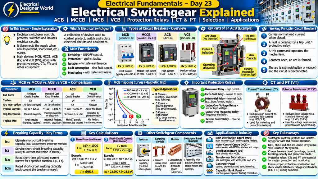
Table of Contents
Simple Explanation
Think of electrical switchgear as the control and safety system of an electrical installation. It helps switch electrical circuits ON and OFF, isolate equipment for maintenance and disconnect the supply when a fault occurs.
You may have seen devices such as MCBs in distribution boards, MCCBs in industrial panels and ACBs in low-voltage switchboards. VCBs are commonly used in medium-voltage systems.
Each device has a specific purpose. Understanding the differences is important for electrical engineers working with distribution boards, motor control centres (MCCs), substations and industrial power systems.
Introduction
Electrical power systems need equipment to control, protect and isolate electrical circuits. This equipment is collectively known as switchgear.
Switchgear is used in residential buildings, commercial facilities, industrial plants, power stations and substations.
It includes circuit breakers, switches, isolators, protective relays, current transformers, voltage transformers, busbars and other associated components.
When an electrical fault occurs, the protection system detects the abnormal condition and sends a trip command to the appropriate circuit breaker. The breaker opens its contacts and interrupts the current, provided the fault is within its rated interrupting capability.
In this lesson, we will understand:
- What electrical switchgear is.
- Why switchgear is important.
- What MCB, MCCB, ACB and VCB mean.
- The difference between circuit breakers.
- How circuit breakers operate.
- What protective relays do.
- The functions of CTs and PTs.
- Breaking capacity and short-circuit ratings.
- Important switchgear calculations.
- Switchgear applications in EPC projects.
- What to check in switchgear vendor documents.
1. What Is Electrical Switchgear?
Electrical switchgear is a collection of electrical devices used to control, protect, switch and isolate electrical circuits and equipment.
It helps ensure that electrical power is distributed safely and reliably.
Main Functions of Switchgear
1. Switching
Switchgear allows electrical circuits to be switched ON and OFF during normal operation.
2. Protection
It helps disconnect circuits when abnormal conditions such as overloads and short circuits occur.
3. Isolation
It provides a means of isolating electrical equipment for inspection and maintenance.
4. Fault Interruption
Circuit breakers interrupt fault current when their protection system operates and the breaker is rated for the fault duty.
5. Monitoring and Control
Switchgear may include meters, relays, indication lamps, control switches and communication systems to monitor electrical conditions.
2. Main Types of Electrical Switchgear
Switchgear is commonly classified according to its voltage level and application.
A. Low-Voltage (LV) Switchgear
Low-voltage switchgear is used in electrical systems up to 1,000 V AC under the relevant IEC low-voltage circuit-breaker standard.
Common equipment includes:
- MCB – Miniature Circuit Breaker.
- MCCB – Moulded Case Circuit Breaker.
- ACB – Air Circuit Breaker.
- Contactors.
- Switch-disconnectors.
- Fuse units.
- Protective relays.
Applications include distribution boards, motor control centres, main distribution boards and industrial control panels.
B. Medium-Voltage (MV) Switchgear
Medium-voltage switchgear is used in systems above low-voltage limits and up to the voltage level specified for the particular installation and standard.
Common equipment includes:
- VCB – Vacuum Circuit Breaker.
- SF6 circuit breakers in applicable designs.
- Load-break switches.
- Isolators.
- Earthing switches.
- Current transformers.
- Voltage transformers.
- Protection relays.
Applications include industrial substations, transformer feeders, incoming utility supplies and distribution networks.
Important: Equipment selection must be based on the system voltage, rated current, fault level, insulation requirements and applicable standards. Do not select switchgear based only on its name or typical application.
3. What Is an MCB (Miniature Circuit Breaker)?
An MCB is a low-voltage circuit breaker commonly used to protect final electrical circuits against overloads and short circuits.
It is commonly installed in residential distribution boards, commercial panels and small electrical distribution systems.
How Does an MCB Work?
An MCB generally uses two tripping mechanisms:
1. Thermal Protection
A bimetallic element heats and bends when excessive current flows for a sufficient period. This causes the breaker to trip during an overload condition.
2. Magnetic Protection
An electromagnetic mechanism operates rapidly when a high short-circuit current flows.
Main Features of an MCB
- Compact construction.
- Thermal and magnetic protection.
- Commonly available in different pole configurations.
- Fixed or specified tripping characteristics.
- Used for final circuit protection.
Common MCB Tripping Curves
| Curve | Typical Magnetic Trip Range | Common Application |
|---|---|---|
| B | 3–5 times rated current | Loads with relatively low inrush current |
| C | 5–10 times rated current | General-purpose circuits and moderate inrush |
| D | 10–20 times rated current | Loads with high inrush current |
These are typical characteristic ranges, not a substitute for the manufacturer’s time-current curves.
Applications of MCB
- Lighting circuits.
- Socket outlet circuits.
- Small distribution boards.
- Small control circuits.
- Suitable low-current equipment feeders.
4. What Is an MCCB (Moulded Case Circuit Breaker)?
An MCCB is a low-voltage circuit breaker housed in a moulded insulating case.
It is commonly used in industrial and commercial electrical distribution systems where higher current ratings and greater fault-interrupting capabilities may be required than those provided by typical MCBs.
Main Features of MCCB
- Higher current ratings than many MCB ranges.
- Higher short-circuit breaking capacities in suitable models.
- Thermal-magnetic or electronic trip units.
- Adjustable protection settings in selected models.
- Different pole configurations.
- Accessories for remote operation and indication in selected designs.
How Does an MCCB Work?
When an overload or short-circuit condition occurs, the MCCB trip mechanism operates according to its trip-unit characteristics.
The breaker opens its contacts and interrupts the current.
Types of MCCB Trip Units
1. Thermal-Magnetic Trip Unit
Uses thermal protection for overloads and magnetic protection for short circuits.
2. Electronic Trip Unit
Uses electronic sensing and processing to provide configurable protection functions.
Applications of MCCB
- Industrial distribution panels.
- Motor feeders.
- Capacitor bank feeders.
- Generator outgoing feeders.
- Sub-distribution boards.
- Transformer secondary feeders.
The exact application depends on the rated current, fault level, protection requirements and coordination study.
5. What Is an ACB (Air Circuit Breaker)?
An ACB is a low-voltage circuit breaker that uses air as the medium for arc interruption.
It is commonly used in main low-voltage switchboards and high-current distribution systems.
ACBs are often installed as incomer, bus-coupler or outgoing breakers in industrial switchboards.
Main Parts of an ACB
- Main contacts.
- Arcing contacts.
- Arc chutes.
- Operating mechanism.
- Trip unit.
- Closing mechanism.
- Auxiliary contacts.
- Racking mechanism in withdrawable designs.
- Trip and closing coils.
- Control and indication accessories.
How Does an ACB Work?
Step 1: The ACB is closed and carries the normal load current.
Step 2: A protection relay or trip unit monitors the current and other specified electrical conditions.
Step 3: When a fault exceeds the configured protection criteria, a trip command is generated.
Step 4: The operating mechanism opens the breaker contacts.
Step 5: An arc forms as the contacts separate.
Step 6: The arc is controlled and extinguished by the arc interruption arrangement.
The circuit is disconnected when the interruption process is successfully completed.
Types of ACB
- Fixed-type ACB.
- Draw-out or withdrawable ACB.
A draw-out ACB can be moved between defined service, test and isolated positions according to its design and interlocking arrangements.
Applications of ACB
- Main LT panel incomers.
- Generator incomers.
- Bus couplers.
- Main distribution boards.
- Large industrial feeders.
6. What Is a VCB (Vacuum Circuit Breaker)?
A VCB is a circuit breaker that uses a vacuum interrupter to extinguish the electrical arc when its contacts separate.
It is widely used in medium-voltage electrical distribution systems.
How Does a VCB Work?
Step 1: The VCB carries normal operating current through its closed contacts.
Step 2: A protective relay detects a fault condition.
Step 3: The relay sends a trip command to the VCB operating mechanism.
Step 4: The breaker contacts separate inside the vacuum interrupter.
Step 5: An arc forms between the contacts.
Step 6: The vacuum interrupter extinguishes the arc as the current passes through its natural current zero in an AC system and the dielectric strength recovers.
The breaker interrupts the fault current within its rated capability.
Main Components of VCB
- Vacuum interrupter.
- Fixed contact.
- Moving contact.
- Operating mechanism.
- Insulating supports.
- Trip coil.
- Closing coil.
- Auxiliary contacts.
- Mechanical position indicators.
Applications of VCB
- Medium-voltage switchgear panels.
- Transformer feeders.
- Motor feeders.
- Industrial substations.
- Incoming utility feeders.
- Distribution networks.
7. Difference Between MCB, MCCB, ACB and VCB
| Parameter | MCB | MCCB | ACB | VCB |
|---|---|---|---|---|
| Full form | Miniature Circuit Breaker | Moulded Case Circuit Breaker | Air Circuit Breaker | Vacuum Circuit Breaker |
| Typical system | LV | LV | LV | MV |
| Arc interruption | Air/arc chamber arrangement | Air/arc chamber arrangement | Air | Vacuum interrupter |
| Typical application | Final circuits | Industrial feeders | Main LV switchboards | MV distribution |
| Trip mechanism | Usually thermal-magnetic | Thermal-magnetic or electronic | Often electronic trip unit | Operated by protective relay |
| Current range | Generally lower | Medium to high, depending on model | High-current applications | Depends on MV equipment design |
| Common installation | DB | MCC or distribution panel | LT switchboard | MV switchgear panel |
Remember: These devices are not interchangeable. Select a breaker based on voltage, current, fault level, protection requirements, installation conditions and applicable standards.
8. What Is a Circuit Breaker’s Breaking Capacity?
Breaking capacity is the maximum fault current that a circuit breaker is designed and tested to interrupt under specified conditions.
It is one of the most important parameters when selecting switchgear.
If the prospective short-circuit current at the installation point exceeds the breaker’s rated breaking capacity, the breaker may not safely interrupt the fault.
Important Breaking Capacity Terms
1. Icu – Ultimate Short-Circuit Breaking Capacity
The rated ultimate short-circuit breaking capacity of a circuit breaker under the specified test conditions.
2. Ics – Service Short-Circuit Breaking Capacity
The rated service short-circuit breaking capacity. It relates to the breaker’s ability to interrupt specified fault current and remain suitable for continued service according to the relevant test requirements.
3. Icw – Rated Short-Time Withstand Current
The current a circuit breaker or switchgear assembly can withstand for a specified short duration under defined conditions.
This is especially important when evaluating selectivity and short-time delay protection.
4. Icm – Rated Short-Circuit Making Capacity
The peak current a circuit breaker can make onto a short circuit under specified conditions.
Example
Suppose the calculated prospective short-circuit current at a panel is 35 kA.
The selected circuit breaker must have an appropriate rated short-circuit breaking capacity for the system voltage and applicable standard that is not less than the required fault duty.
The final selection must also consider Ics, Icw where relevant, protection coordination and the switchboard assembly rating.
9. What Is a Protective Relay?
A protective relay is an electrical device that monitors system quantities such as current, voltage, frequency and other measured conditions.
When an abnormal condition is detected, the relay operates according to its settings and sends a trip or alarm command.
A protective relay usually does not interrupt the main power circuit directly. It operates the trip circuit of a circuit breaker.
Common Types of Protective Relays
1. Overcurrent Relay
Detects current exceeding a specified threshold.
2. Earth-Fault Relay
Detects current associated with an earth fault.
3. Differential Relay
Compares current entering and leaving a protected zone and detects certain internal faults.
4. Under-Voltage Relay
Detects voltage falling below a specified level.
5. Over-Voltage Relay
Detects voltage exceeding a specified level.
6. Under-Frequency Relay
Detects system frequency falling below a specified value.
7. Over-Frequency Relay
Detects system frequency exceeding a specified value.
8. Reverse Power Relay
Used with generators to detect power flowing in the reverse direction under specified conditions.
Why Are Protective Relays Important?
Protective relays help detect faults and operate the correct circuit breaker to isolate the affected section.
This reduces the risk of equipment damage and helps maintain the continuity of the remaining electrical system.
10. What Are CTs and PTs in Switchgear?
Current transformers and voltage transformers provide scaled electrical signals for measurement, monitoring and protection.
A. Current Transformer (CT)
A CT reduces a high primary current to a smaller secondary current suitable for meters and protective relays.
Example:
A CT ratio of 800/5 means that a primary current of 800 A corresponds to a secondary current of 5 A under the specified ratio conditions.
CTs are used for:
- Ammeter measurements.
- Energy metering.
- Overcurrent protection.
- Earth-fault protection.
- Differential protection.
Important CT safety: Never leave an energised CT secondary open-circuited. Follow the approved shorting and isolation procedures when disconnecting CT secondary circuits.
B. Potential Transformer (PT) / Voltage Transformer (VT)
A PT or VT reduces a high primary voltage to a lower standard secondary voltage suitable for measurement and protection.
It is used for:
- Voltmeter measurements.
- Voltage monitoring.
- Under-voltage protection.
- Over-voltage protection.
- Synchronising circuits.
- Frequency and power measurement.
Difference Between CT and PT
| Parameter | CT | PT / VT |
|---|---|---|
| Full form | Current Transformer | Potential / Voltage Transformer |
| Measures | Current | Voltage |
| Connection | In series with the primary circuit | In parallel with the primary circuit |
| Output | Standardised current | Standardised voltage |
| Application | Current measurement and protection | Voltage measurement and protection |
11. What Is an Isolator?
An isolator is a mechanical switching device used to isolate part of an electrical installation from its source.
It is generally intended to operate when no load current is being interrupted, unless it is specifically designed and rated for load switching.
An isolator provides a visible or otherwise verifiable isolation gap depending on its design.
Main Functions
- Isolating equipment for maintenance.
- Separating electrical sections.
- Providing an isolation point.
- Supporting safe maintenance procedures.
Important: An isolator is not a substitute for a circuit breaker. It should not be used to interrupt fault current.
12. What Is an Earthing Switch?
An earthing switch is a switching device used to connect an isolated part of an electrical circuit to earth.
It is used in medium-voltage and high-voltage switchgear arrangements to provide an earth connection for safe maintenance.
It helps discharge induced or residual charges and establish an earthed condition when used as part of an approved isolation procedure.
Earthing switches must be operated only in accordance with the equipment interlocks and site safety procedures.
13. What Is an Electrical Busbar?
A busbar is a conductor used to collect and distribute electrical power within a switchboard or substation.
Busbars are commonly made from copper or aluminium.
They are installed inside electrical panels and connect incoming and outgoing feeders.
Types of Busbar Arrangements
- Single busbar.
- Single busbar with sectionalisation.
- Double busbar.
- Main and transfer busbar.
- Ring bus arrangement.
The busbar arrangement is selected based on reliability, flexibility, maintenance requirements, cost and project design.
Important Busbar Parameters
- Rated current.
- Rated short-time withstand current.
- Rated peak withstand current.
- Material.
- Cross-sectional dimensions.
- Temperature rise.
- Insulation and clearance requirements.
- Enclosure and installation conditions.
14. What Is a Switchgear Panel?
A switchgear panel is an assembly that contains switching, control, measurement and protection equipment.
A typical industrial low-voltage switchboard may contain:
- Main incomer ACB.
- Busbar system.
- Outgoing MCCBs.
- Metering equipment.
- Current transformers.
- Protective relays.
- Indication lamps.
- Control switches.
- Bus coupler.
- Cable termination compartments.
A medium-voltage panel may contain:
- VCB.
- CTs.
- VTs, where required.
- Protection relay.
- Busbar compartment.
- Cable compartment.
- Earthing switch.
- Operating mechanism.
- Interlocking arrangement.
The actual panel arrangement depends on the single-line diagram, technical specification and equipment design.
15. Important Switchgear Calculations
Electrical engineers need to understand load current and fault current before selecting switchgear.
1. Three-Phase Load Current
For a balanced three-phase load:
I = kVA × 1000 ÷ (1.732 × V)
Where:
- I = Line current in amperes.
- kVA = Apparent power.
- V = Line-to-line voltage in volts.
Example
Consider a three-phase load of 500 kVA connected to a 415 V supply.
I = 500 × 1000 ÷ (1.732 × 415)
I ≈ 695 A.
Therefore, the calculated load current is approximately 695 A.
This is not by itself a final breaker selection. The design must also consider load characteristics, cable ampacity, ambient temperature, installation conditions, protection settings, fault level and coordination.
2. Short-Circuit Current
For a simplified three-phase system at the transformer secondary terminals, assuming an infinite upstream supply and neglecting upstream impedance:
Isc ≈ (Transformer kVA × 1000) ÷ (1.732 × Voltage × (Z% ÷ 100))
Where:
- Isc = Approximate short-circuit current in amperes.
- Transformer kVA = Transformer rating.
- Voltage = Secondary line voltage in volts.
- Z% = Transformer percentage impedance.
Example
Assume:
- Transformer rating = 1000 kVA.
- Secondary voltage = 415 V.
- Transformer impedance = 6%.
Isc ≈ (1000 × 1000) ÷ (1.732 × 415 × 0.06)
Isc ≈ 23,200 A or 23.2 kA.
This is an approximate fault current at the transformer terminals under the stated assumptions.
Actual fault current depends on upstream source impedance, cable impedance, motor contribution and the complete network configuration. A proper short-circuit study is required for final switchgear selection.
16. What Is Protection Coordination?
Protection coordination is the process of selecting and setting protective devices so that the device closest to a fault operates first, wherever practical and required.
For example, if a fault occurs on an outgoing feeder, the feeder protective device should normally clear the fault without unnecessarily tripping the main incomer.
Why Is Coordination Important?
- Improves continuity of supply.
- Limits the area affected by a fault.
- Reduces unnecessary shutdowns.
- Helps protect cables and equipment.
- Supports safe and reliable system operation.
Coordination is checked using time-current characteristic curves, manufacturer selectivity tables and electrical system studies.
17. What Is an Arc Flash?
An arc flash is a dangerous release of energy caused by an electrical arc.
It can produce intense heat, pressure, light and molten metal.
Arc flash hazards may occur during equipment faults, switching or maintenance activities.
Arc Flash Safety
- Follow the approved electrical safety procedure.
- Perform arc-flash risk assessment where required.
- Use appropriate PPE based on the assessment.
- Maintain safe working distances.
- Keep switchgear doors and covers secured during normal operation.
- Follow approved switching procedures.
- Never bypass electrical or mechanical interlocks.
- Only qualified and authorised personnel should operate or maintain switchgear.
18. What Should an Electrical Engineer Check in a Switchgear Datasheet?
When reviewing switchgear vendor documents in an EPC project, check the following:
| Parameter | What to Check |
|---|---|
| Equipment type | ACB, MCCB, MCB or VCB |
| Rated voltage | System operating voltage |
| Rated current | Continuous current rating |
| Frequency | 50 Hz or specified project frequency |
| Number of poles | 1P, 2P, 3P or 4P as applicable |
| Breaking capacity | Icu, Ics or relevant breaker rating |
| Short-time withstand | Icw and duration where applicable |
| Making capacity | Icm where applicable |
| Trip unit | Thermal-magnetic or electronic |
| Protection functions | L, S, I, G or other specified functions |
| CT ratio | Primary and secondary current ratings |
| VT ratio | Primary and secondary voltage ratings |
| Busbar rating | Rated current and fault withstand |
| Installation | Fixed, plug-in or withdrawable |
| IP rating | Enclosure protection |
| Control voltage | Trip, close and auxiliary circuit voltage |
| Interlocking | Electrical and mechanical interlocks |
| Standards | Applicable IEC and IS requirements |
| Accessories | Auxiliary contacts, shunt trip, UV release and other accessories |
Always check the approved datasheet, single-line diagram, schematic diagrams, protection philosophy, short-circuit study and project specifications.
19. Switchgear Applications in EPC Electrical Projects
Switchgear is used throughout industrial and infrastructure projects.
1. Main Distribution Board (MDB)
The MDB receives power from a transformer or generator and distributes it to downstream panels.
It may contain an ACB incomer and MCCB outgoing feeders, depending on the design.
2. Motor Control Centre (MCC)
MCC panels supply and control motors.
They may contain MCCBs, contactors, overload relays, motor protection relays, soft starters and VFDs.
3. Distribution Board (DB)
Distribution boards distribute power to lighting, socket and other final circuits.
MCBs and suitable residual-current protection devices may be used according to the circuit design.
4. Transformer Substation
Medium-voltage switchgear controls and protects transformer feeders.
VCBs, protection relays, CTs, VTs and earthing switches may be part of the installation.
5. Generator Panel
Generator switchgear connects generators to the electrical system and provides switching, protection, metering and synchronising functions as required.
6. Capacitor Bank Panel
Capacitor bank panels use suitable switching and protective devices to connect and disconnect capacitor steps for power factor correction.
20. Frequently Asked Questions
1. What is the main function of electrical switchgear?
Switchgear controls, protects, switches and isolates electrical circuits and equipment.
2. What is the difference between MCB and MCCB?
MCBs are commonly used for final circuit protection, while MCCBs are used in a wider range of industrial and commercial feeder applications with different current ratings and protection options.
3. What is the difference between ACB and VCB?
An ACB uses air as its arc-interruption medium and is commonly used in low-voltage switchboards. A VCB uses a vacuum interrupter and is widely used in medium-voltage switchgear.
4. What is breaking capacity?
Breaking capacity is the rated fault current a circuit breaker can safely interrupt under specified conditions.
5. What is the function of a protective relay?
A protective relay detects abnormal electrical conditions and sends a trip or alarm command to the relevant circuit breaker or control system.
6. What is a CT?
A current transformer reduces a high current to a standard lower current for measurement and protection.
7. What is a PT or VT?
A potential transformer or voltage transformer reduces a high voltage to a lower standard voltage for measurement and protection.
8. Can an isolator interrupt short-circuit current?
A normal isolator is not designed to interrupt short-circuit current. A suitably rated circuit breaker is used for fault interruption.
9. What is a busbar?
A busbar is a conductor that collects and distributes electrical power within a panel or substation.
10. What is protection coordination?
Protection coordination ensures that protective devices operate in a planned sequence so that the device nearest to the fault disconnects the affected circuit wherever practical.
21. Practice Questions
Test your understanding of electrical switchgear.
Question 1: What is the main purpose of electrical switchgear?
A. Generate electricity
B. Control, protect and isolate electrical circuits
C. Store electrical energy
D. Convert AC into DC
Question 2: Which breaker is commonly used in final distribution circuits?
A. VCB
B. MCB
C. ACB
D. Generator breaker
1. IEC – Low-Voltage Circuit Breakers
For the international requirements and technical scope of low-voltage circuit breakers, refer to IEC 60947-2: Low-Voltage Switchgear and Controlgear – Circuit Breakers.
2. IEC – Medium-Voltage Circuit Breakers
To learn about the applicable requirements for AC circuit breakers used in systems above 1,000 V, refer to IEC 62271-100: High-Voltage Switchgear and Controlgear – AC Circuit Breakers.
3. Bureau of Indian Standards (BIS) – Switchgear Standards
For Indian standards and certification information related to low-voltage switchgear and controlgear, explore the BIS Product-Specific Information.
4. Siemens – Switchgear and Substations
For further technical reading about switchgear selection, circuit breakers and substation arrangements, refer to the Siemens Power Engineering Guide.