
How to Read a Transformer on an Electrical SLD
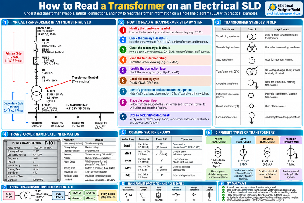
Table of Contents
How to read a transformer on an electrical SLD is an essential skill for electrical engineers and designers working on industrial Engineering, Procurement, and Construction (EPC) projects. A transformer transfers electrical power between circuits and changes the voltage level according to the electrical distribution requirements.
In a typical industrial electrical Single Line Diagram (SLD), a transformer connects an incoming supply to a downstream distribution system. Its symbol and equipment label may provide information about the voltage ratio, power rating, winding connection, vector group, and other important design details.
Learning to read a transformer on an electrical SLD helps you understand the power distribution hierarchy, identify the correct transformer, trace power to switchboards, and coordinate the load list, transformer datasheet, and electrical equipment schedules.
For more practical electrical engineering lessons, visit Electrical Designer World.
What Is a Transformer in an Electrical SLD?
A transformer is an electrical device that transfers energy between circuits through electromagnetic induction. A power transformer commonly steps voltage up or down to suit the transmission or distribution system.
In an industrial SLD, the transformer is represented by a standard or project-specific symbol, commonly showing two overlapping circles for a two-winding transformer. The drawing may also include a transformer tag and its main electrical ratings.
For example:
T-101 | 11/0.415 kV | 1.5 MVA | Dyn11
This example identifies a transformer with an 11 kV primary voltage, a 415 V secondary voltage, a 1.5 MVA rating, and a Dyn11 vector group.
These values are illustrative. Always verify actual transformer details against the approved SLD and transformer datasheet.
Why Is Reading a Transformer SLD Important for EPC Electrical Designers?
Understanding a transformer in an SLD helps you perform several important electrical design tasks.
1. Understand the voltage distribution hierarchy
You can identify where the voltage is stepped down or stepped up and determine which downstream switchboard receives the transformer supply.
2. Verify transformer ratings
You can read the transformer’s voltage and power ratings and compare them with the electrical load requirements and approved datasheet.
3. Understand winding connections
The vector group indicates the winding connection arrangement and phase displacement between the high-voltage and low-voltage sides. This is important when evaluating transformer connections and parallel operation.
4. Trace downstream electrical loads
The transformer secondary may supply a low-voltage PCC, switchboard, MCC, or another distribution assembly.
5. Coordinate electrical documents
Transformer details must agree with the load list, transformer datasheet, SLD, switchboard schedule, and relevant protection and cable calculations.
How to Identify a Transformer Symbol in an Electrical SLD
A transformer symbol is commonly shown as two overlapping circles, although the exact representation depends on the drawing standard and winding arrangement.
When you locate the symbol, look for the following information:
- Transformer equipment tag, such as T-101.
- Primary or high-voltage rating.
- Secondary or low-voltage rating.
- Transformer capacity in kVA or MVA.
- Vector group, where shown.
- Frequency and phase information, where shown.
- Cooling method, impedance, or other ratings when included.
The transformer symbol tells you where the transformer is located in the power distribution path. The accompanying text provides its identification and technical ratings.
For standardized electrical drawing references, consult the International Electrotechnical Commission (IEC). Always use the legend and symbol conventions specified for your project.
How to Read a Transformer on an Electrical SLD: Step by Step
Consider an industrial plant where an 11 kV supply is stepped down to 415 V for low-voltage distribution.
Step 1: Identify the transformer symbol
Locate the transformer symbol in the SLD. A conventional two-winding transformer is often shown as two overlapping circles.
Find the transformer tag, such as T-101, so that you can identify the same equipment in other project documents.
Step 2: Read the primary voltage
The primary side is the winding connected to the incoming supply in the specified operating arrangement.
For example:
Primary voltage = 11 kV
This means the transformer is designed for an 11 kV primary system under its specified operating conditions.
Do not assume the primary side is always drawn on the left or at the top. Follow the incoming electrical connection and the drawing labels.
Step 3: Read the secondary voltage
The secondary side supplies the downstream electrical distribution system.
For example:
Secondary voltage = 0.415 kV (415 V)
The transformer steps the voltage down from 11 kV to 415 V in this example.
Check whether the voltage is expressed in kV or V and verify the stated system voltage in the transformer datasheet.
Step 4: Read the transformer power rating
Transformer capacity is usually expressed in kVA or MVA.
For example:
Rated capacity = 1.5 MVA = 1500 kVA
This rating represents the transformer’s apparent power capacity under its specified operating conditions. It is not the same as the real power in kW.
Step 5: Identify the vector group
The vector group describes the winding connections and the phase displacement between the high-voltage and low-voltage windings.
For example, Dyn11 indicates a delta-connected high-voltage winding, a star-connected low-voltage winding with a neutral brought out, and a clock-number designation of 11 for the phase displacement.
Always verify the exact connection and phase relationship from the transformer datasheet and applicable standard.
Step 6: Check the associated protection and switching devices
Depending on the voltage level and design, the transformer circuit may include:
- High-voltage circuit breaker or switchgear.
- Isolator or disconnector.
- Earthing switch.
- Current transformer (CT).
- Voltage transformer (VT).
- Surge arrester.
- Low-voltage main circuit breaker.
- Transformer monitoring or protection devices.
Not every SLD shows all these components. Refer to the relevant protection schematic and project documents where details are missing.
Step 7: Trace the transformer power flow
Follow the incoming supply to the transformer primary and then follow the secondary connection to the downstream busbar or switchboard.
For example:
11 kV Supply → Transformer T-101 → 415 V PCC → MCC and Other Loads
This sequence helps you understand where the transformer sits within the electrical distribution system.
Step 8: Cross-check the transformer datasheet
Finally, compare the SLD information with the approved transformer datasheet and electrical design documents.
Verify the rating, voltage ratio, vector group, impedance, cooling type, tapping arrangement, and other required details wherever applicable.
Practical Transformer SLD Example
The following simplified diagram shows a transformer supplying a low-voltage PCC.
         11 kV INCOMING SUPPLY
                   |
            HV SWITCHGEAR
                   |
              HV BREAKER
                   |
            TRANSFORMER T-101
               11 / 0.415 kV
                  1.5 MVA
                  Dyn11
                   |
              LV MAIN ACB
                   |
             415 V PCC BUSBAR
                   |
          +--------+--------+
          |        |        |
        MCC-01   MCC-02   UTILITY
        MOTORS   MOTORS    LOADS
How to interpret the diagram:
- 11 kV incoming supply: Supplies the transformer primary through the specified high-voltage equipment.
- HV switchgear and breaker: Provide the specified switching and protection arrangement.
- Transformer T-101: Steps the voltage down from 11 kV to 415 V.
- LV main ACB: Provides switching and protection on the low-voltage side according to the design.
- 415 V PCC busbar: Distributes power to downstream feeders.
- MCC-01 and MCC-02: Supply motor loads through their respective feeder arrangements.
- Utility loads: Represent other downstream electrical loads.
This is a learning example, not a construction-approved drawing. The actual protection and switching arrangement must follow the approved project SLD and design.
Understanding Transformer Nameplate Information
A transformer nameplate contains technical information needed for operation, design, and maintenance.
| Parameter | Meaning |
|---|---|
| Transformer tag | Equipment identification, such as T-101 |
| Rated power | Capacity in kVA or MVA |
| Primary voltage | Rated voltage of the primary winding |
| Secondary voltage | Rated voltage of the secondary winding |
| Frequency | System frequency, commonly 50 Hz or 60 Hz |
| Number of phases | Single-phase or three-phase |
| Vector group | Winding connections and phase displacement |
| Impedance | Short-circuit impedance, commonly expressed as a percentage |
| Cooling type | Cooling arrangement, such as ONAN or ONAF |
| Tap changer | Arrangement for adjusting the transformation ratio |
| Temperature rise and insulation | Thermal and insulation-related design information |
| Applicable standard | Standard specified for the transformer |
The SLD may show only a few of these values. The complete transformer datasheet and nameplate should be used for detailed verification.
What Does the Transformer Vector Group Mean?
The vector group is one of the most important transformer details for electrical design.
It indicates the winding connection arrangement and the phase displacement between the primary and secondary voltages.
Example: Dyn11
The designation Dyn11 can be interpreted as follows:
- D: High-voltage winding connected in delta.
- y: Low-voltage winding connected in star.
- n: Neutral point of the low-voltage star winding is brought out.
- 11: Clock notation identifying the phase displacement according to the applicable reference convention.
Vector groups matter when checking phase relationships, earthing arrangements, and suitability for parallel operation.
Transformers must not be assumed suitable for parallel operation simply because their voltage ratings are the same. Their vector groups, ratios, impedances, phase relationships, and other operating requirements must be compatible.
Transformer Cooling Types in Electrical Design
Transformer cooling affects its thermal performance and rated operating capability.
Common oil-immersed transformer cooling designations include:
- ONAN: Oil Natural Air Natural.
- ONAF: Oil Natural Air Forced.
- OFAF: Oil Forced Air Forced.
The cooling method and applicable rating depend on the transformer design and manufacturer specifications.
Do not assume every transformer uses oil cooling. Dry-type transformers use different construction and cooling arrangements.
Common Transformer Types Found in Industrial Electrical Projects
1. Power transformer
Used to transfer electrical power between voltage levels in a power system or industrial distribution network.
2. Distribution transformer
Used to provide the required supply voltage for downstream distribution loads.
3. Auto-transformer
Uses a shared winding arrangement for the primary and secondary circuits. Its design differs from that of a conventional two-winding transformer.
4. Isolation transformer
Provides electrical separation between circuits when designed for that purpose. Isolation alone does not guarantee safety; the complete electrical installation must be designed appropriately.
5. Instrument transformers
Current transformers (CTs) and voltage transformers (VTs) provide scaled electrical signals for metering and protection.
These instrument transformers are different from the main power transformer supplying the plant distribution system.
How Transformer Ratings Relate to Electrical Load
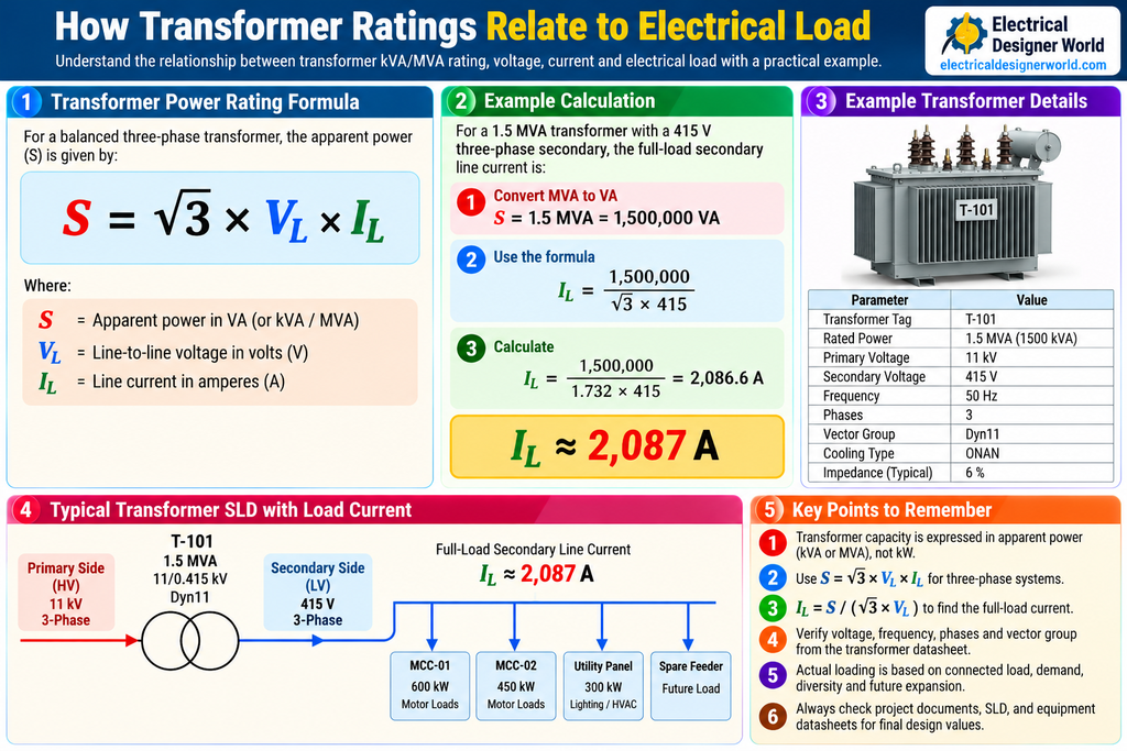
This is an illustrative calculation based on the stated rating and voltage. The actual design must account for nameplate ratings, operating conditions, protection, loading, and applicable requirements.
Transformer selection should consider the expected demand, load characteristics, starting requirements, future expansion, ambient conditions, and project design margins. A simple sum of motor kW ratings is not sufficient on its own.
For additional background on electrical installation design, see Schneider Electric’s Electrical Installation Guide.
Common Mistakes When Reading a Transformer SLD
1. Confusing primary and secondary voltage
Always trace the electrical connections and read the voltage labels. Do not rely only on the symbol’s drawing position.
2. Confusing kVA or MVA with kW
Transformer capacity is normally expressed in apparent power. Real power depends on power factor and operating conditions.
3. Ignoring the vector group
The vector group affects phase relationships and must be checked when evaluating transformer connections and parallel operation.
4. Assuming the transformer symbol shows every detail
An SLD is a simplified representation. The complete transformer datasheet and associated protection drawings provide additional information.
5. Assuming every transformer has the same protection arrangement
Protection depends on voltage level, transformer rating, grounding arrangement, applicable standards, and project requirements.
6. Selecting a transformer based only on connected load
Transformer sizing must consider demand, load characteristics, motor starting, voltage regulation, future requirements, and other design conditions.
7. Ignoring drawing revisions
Always use the latest approved SLD and verify that its transformer ratings match the approved datasheet.
Transformer SLD Review Checklist for EPC Electrical Designers
Use this checklist when reviewing a transformer in an industrial electrical project.
- Transformer tag matches the equipment datasheet.
- Primary and secondary voltages are identified.
- Rated power in kVA or MVA is verified.
- Number of phases and frequency are confirmed.
- Vector group is checked.
- Impedance and cooling type are verified where applicable.
- Tap changer requirements are understood where specified.
- Associated switching and protection equipment is identified.
- Transformer secondary connection to the downstream busbar is traceable.
- Transformer ratings agree with the approved load and design calculations.
- The latest approved drawing revision is being used.
Frequently Asked Questions (FAQs)
1. How do I identify a transformer in an electrical SLD?
Look for the transformer symbol, commonly represented by two overlapping circles for a two-winding transformer. Read its equipment tag, voltage ratio, capacity, and vector group where shown.
2. What does 11/0.415 kV mean on a transformer SLD?
It indicates a rated primary voltage of 11 kV and a rated secondary voltage of 0.415 kV, or 415 V, for the stated transformer configuration.
3. What does 1.5 MVA mean on a transformer?
It represents the transformer’s rated apparent power capacity of 1,500 kVA under its specified operating conditions.
4. What does Dyn11 mean in a transformer?
Dyn11 indicates a delta-connected high-voltage winding, a star-connected low-voltage winding with a neutral brought out, and a clock-number designation of 11 for the phase displacement.
5. What is the difference between a transformer and a CT?
A power transformer transfers electrical power between circuits and may change the voltage level. A current transformer provides a scaled current signal for metering and protection.
6. What equipment is connected after a transformer in an industrial SLD?
A transformer secondary may feed a main low-voltage circuit breaker and busbar, which then supplies a PCC, MCC, or other downstream loads. The exact arrangement depends on the project design.
7. Which documents should I check after reading a transformer SLD?
Check the transformer datasheet, electrical load list, electrical design basis, protection drawings, switchboard schedules, and relevant project specifications.
Conclusion
Learning how to read a transformer on an electrical SLD helps electrical designers understand voltage transformation, transformer capacity, winding connections, and the distribution of power to downstream electrical equipment.
Start by identifying the transformer symbol and tag, read the primary and secondary voltages, check the MVA rating and vector group, and trace the connections to the downstream switchboard.
Finally, verify the information against the approved transformer datasheet and project documents before using it for electrical design calculations or equipment selection.
For more practical electrical engineering lessons, visit Electrical Designer World.