
Electrical SLD Symbols: 15 Essential Symbols Explained
Understanding electrical SLD symbols is essential for reading industrial power distribution drawings. These symbols represent transformers, circuit breakers, busbars, protection relays and other electrical equipment used in EPC projects. Learning electrical SLD symbols helps electrical designers trace power flow and understand how equipment is connected.
Table of Contents
Electrical SLD symbols help electrical engineers understand how power flows through an electrical distribution system. When you open an industrial drawing, you may see transformers, circuit breakers, busbars, current transformers, protection relays and many other symbols.
Learning electrical SLD symbols is an essential skill for electrical designers working in EPC (Engineering, Procurement and Construction) projects. These symbols allow you to understand the electrical connections without drawing every conductor and component in detail.
In this guide, we will explain 15 important electrical SLD symbols and abbreviations, their functions, and how to identify them in practical industrial drawings.
What Are Electrical SLD Symbols?
Electrical SLD symbols are graphical representations of electrical equipment and components used in a Single Line Diagram (SLD).
An SLD simplifies a power system by representing its main connections and equipment using a single-line format. It may show the incoming supply, transformers, switchgear, busbars, feeders, protection devices and connected loads.
The symbols help engineers understand:
- Where electrical power enters the system
- How voltage is transformed
- Which devices switch or protect electrical circuits
- How power is distributed through busbars and feeders
- Which electrical equipment receives power
The exact appearance of a symbol can vary according to the applicable drawing standard, project convention and manufacturer documentation. Always refer to the legend provided with the drawing.
If you are new to SLD reading, first study our complete guide to reading an electrical SLD in EPC projects. This article focuses specifically on recognising the symbols and abbreviations used in those drawings.
Electrical SLD Symbols: 15 Essential Symbols Explained
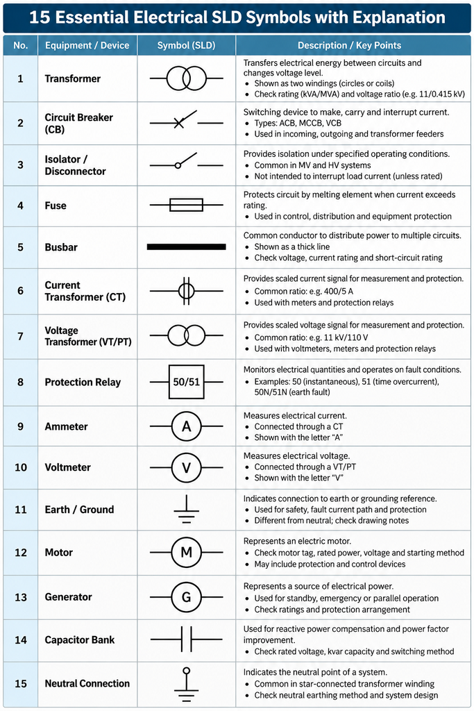
1. Transformer Symbol
A transformer is used to transfer electrical energy between circuits and change the voltage level according to its winding ratio.
On an SLD, a transformer is commonly represented using two winding symbols, often drawn as circles or curved lines, depending on the drawing convention.
For example, an industrial SLD may show an 11/0.415 kV transformer supplying a 415 V low-voltage switchboard.
When reading a transformer symbol, check:
- Transformer tag number
- Rated power in kVA or MVA
- Primary and secondary voltages
- Winding connection or vector group, if shown
- Impedance and earthing details, where specified
2. Circuit Breaker Symbol
A circuit breaker is a switching device capable of making, carrying and interrupting current under specified operating conditions.
Common abbreviations include:
- ACB — Air Circuit Breaker
- MCCB — Moulded Case Circuit Breaker
- VCB — Vacuum Circuit Breaker
The abbreviation and symbol help identify the type of device shown in the drawing.
In an EPC project, circuit breakers may be installed in incoming feeders, outgoing feeders, transformer circuits and motor feeders.
Do not select a breaker based only on its symbol. Its current rating, breaking capacity, protection functions and operating conditions must be verified through engineering calculations and project specifications.
3. Isolator or Disconnector Symbol
An isolator, also called a disconnector, is used to establish an isolation gap under its specified operating conditions.
It is commonly found in medium-voltage and high-voltage electrical systems.
An isolator should not automatically be treated as a circuit breaker. A conventional isolator is not intended to interrupt normal load current unless it is specifically designed and rated for that duty.
When reading an SLD, check the device identification and associated switching arrangement.
4. Fuse Symbol
A fuse protects an electrical circuit by melting its element when current exceeds its specified operating characteristics.
Fuses may be used in control circuits, distribution systems and equipment protection arrangements.
In an SLD, identify the fuse symbol along with its rating and the equipment it protects, where that information is provided.
A fuse’s selection depends on its voltage rating, current rating, breaking capacity, operating characteristics and coordination with other protective devices.
5. Busbar Symbol
A busbar is a common conductor used to distribute electrical power to multiple circuits within a switchboard or distribution assembly.
In many SLDs, it is represented by a thick horizontal or vertical line.
For example, a 415 V busbar may supply several outgoing feeders connected to an MCC, distribution board and auxiliary panel.
Important busbar information includes:
- Rated voltage
- Continuous current rating
- Short-circuit withstand rating
- Bus section arrangement
- Connected incoming and outgoing feeders
A busbar is a central feature of an electrical distribution diagram because it connects the supply to multiple outgoing circuits.
6. Current Transformer (CT) Symbol
A Current Transformer (CT) provides a scaled current signal for measurement and protection.
CTs are commonly associated with ammeters, energy meters and protection relays.
For example, a CT may provide current information to an overcurrent protection relay, which can issue a trip command to the associated circuit breaker when its configured protection criteria are met.
When reading a CT symbol, check its ratio, accuracy class, core allocation and connected equipment if these details are included in the drawing or supporting documents.
7. Voltage Transformer (VT/PT) Symbol
A Voltage Transformer (VT), also known as a Potential Transformer (PT), provides a scaled voltage signal for measurement and protection.
It may be used with voltmeters, metering equipment and protection relays.
In a medium-voltage switchgear SLD, a VT may be connected to the busbar or another specified point in the system.
Remember:
- CT — Current measurement signal
- VT/PT — Voltage measurement signal
The symbol alone does not tell you the complete instrument-transformer specification. Check the relevant equipment data and drawing notes.
8. Protection Relay Symbol
A protection relay monitors electrical quantities and operates according to its configured protection functions.
Depending on the application, it may provide protection against overcurrent, earth faults, differential faults or other abnormal conditions.
The SLD may identify the relay by its tag number or ANSI device number.
Common examples include:
- 50 — Instantaneous overcurrent relay function
- 51 — Time overcurrent relay function
- 50N/51N — Commonly used designations for neutral or earth-fault overcurrent functions, depending on the scheme
Always check the protection legend and relay specification because the exact application and settings depend on the system design.
9. Ammeter Symbol
An ammeter measures electrical current.
In an SLD, it may be shown as an instrument symbol with the letter A, or identified by a tag or instrument designation.
An ammeter may receive its measurement signal from a CT rather than being connected directly to the main power circuit.
Check the measurement point and CT arrangement when interpreting the drawing.
10. Voltmeter Symbol
A voltmeter measures electrical voltage.
It is often represented by an instrument symbol containing the letter V, depending on the drawing convention.
In a switchboard, a voltmeter may be connected through a voltage transformer or another approved measurement arrangement, depending on the system voltage and design.
11. Earth or Ground Symbol
The earth symbol identifies an electrical connection to earth or a designated grounding reference.
Earthing is important for electrical safety, fault-current paths and the correct operation of protection systems.
However, protective earth, neutral and functional earth are not automatically interchangeable. Their purpose and connections must be confirmed from the drawing and earthing design.
12. Motor Symbol
A motor symbol identifies an electric motor connected to the distribution system.
The motor may be represented by a circle containing the letter M or by another project-defined symbol.
Industrial motor feeders may include a circuit breaker, contactor, overload protection, starter or variable-frequency drive, depending on the application.
When reading a motor feeder, check the motor tag, rated power, supply voltage, starting method and protective arrangement.
13. Generator Symbol
A generator symbol represents a source of electrical power.
Industrial plants may use generators for standby, emergency or other specified operating modes.
An SLD may show the generator connected to a switchboard through a circuit breaker and associated switching or transfer arrangement.
Do not assume the generator can operate in parallel with the utility supply simply because both sources appear on the same diagram. The operating philosophy and protection arrangements must be checked.
14. Capacitor Bank Symbol
A capacitor bank is commonly used for reactive-power compensation and power-factor improvement.
In industrial electrical systems, capacitor banks may be connected to a busbar or distribution panel.
Before interpreting a capacitor-bank arrangement, check its rated voltage, kvar capacity, switching method and any associated harmonic mitigation requirements.
The presence of a capacitor bank does not by itself establish that the system’s power factor or harmonic performance is satisfactory.
15. Neutral Connection Symbol
A neutral connection is associated with the neutral point of a system, commonly in a star-connected transformer winding or other suitable source arrangement.
The neutral conductor and protective earth conductor serve different functions and must be identified correctly.
In an SLD, check the transformer winding connection, neutral earthing method and the neutral connections shown for the downstream distribution system.
Not every three-phase system uses a distributed neutral conductor, so follow the actual design rather than assuming one is always present.
Common Electrical SLD Abbreviations
In addition to graphical symbols, electrical SLDs use abbreviations to identify equipment and circuit functions.
| Abbreviation | Full form |
|---|---|
| SLD | Single Line Diagram |
| TX | Transformer; confirm project convention |
| CB | Circuit Breaker |
| ACB | Air Circuit Breaker |
| MCCB | Moulded Case Circuit Breaker |
| VCB | Vacuum Circuit Breaker |
| CT | Current Transformer |
| VT | Voltage Transformer |
| PT | Potential Transformer |
| PCC | Power Control Centre |
| MCC | Motor Control Centre |
| UPS | Uninterruptible Power Supply |
| ATS | Automatic Transfer Switch |
| DG | Diesel Generator; confirm project convention |
| DB | Distribution Board |
| M | Motor; confirm the symbol legend |
| N | Neutral; confirm the drawing convention |
| PE | Protective Earth |
Abbreviations can differ between projects and companies. Always use the project’s abbreviation list and drawing legend as the final reference.
How to Read Electrical SLD Symbols in a Practical EPC Example
Consider a simplified industrial power distribution system:
Utility Supply → Incoming Circuit Breaker → Transformer → Main LV Busbar → MCC → Motor Feeder → Motor.
Follow these steps when reading the drawing.
Step 1: Identify the source. Locate the utility supply and the incoming voltage.
Step 2: Find the incoming switching device. Identify the circuit breaker and any associated metering or protection.
Step 3: Locate the transformer. Read its voltage ratio and rating.
Step 4: Identify the busbar. Check the voltage level and the connected outgoing feeders.
Step 5: Follow the feeder. Trace the connection from the busbar to the MCC or other downstream panel.
Step 6: Identify the motor circuit. Check the motor tag and the associated switching and protection arrangement.
Step 7: Verify the drawing notes. Read the symbol legend, equipment ratings, revision and relevant design notes.
For example, an SLD might show an 11 kV incoming supply feeding an 11/0.415 kV transformer. The transformer secondary may supply a 415 V switchboard, which then feeds an MCC and individual motor circuits.
These are illustrative values. The actual equipment ratings and connections depend on the project’s electrical design.
How SLD Symbols Connect to Other EPC Electrical Documents
SLD symbols provide the system overview, but additional documents are needed for detailed engineering.
For example, a motor symbol may identify the connected load, while the motor data sheet provides the equipment rating and operating requirements.
The feeder information can then be checked against the cable schedule and associated calculations.
To continue learning, read our guides on cable sizing in EPC electrical projects and short-circuit calculation in EPC electrical projects.
These topics explain how the electrical distribution arrangement connects with cable selection, fault-current calculations and protective-device requirements.
Authoritative References for Electrical Drawings and Standards
Electrical symbols should be interpreted using the applicable drawing standard and project documentation.
For additional technical reference, consult:
- International Electrotechnical Commission (IEC) standards for international electrotechnical standards.
- IEC Webstore to identify relevant published standards and their editions.
- Electrical Installation Guide — Electrical regulations and standards for background on electrical installation regulations and standards.
The applicable standard depends on the project scope and jurisdiction. These resources are references, not substitutes for the project’s approved engineering specifications.
Frequently Asked Questions
1. What are electrical SLD symbols?
Electrical SLD symbols are graphical representations of equipment and components in a Single Line Diagram, such as transformers, circuit breakers, busbars, relays and motors.
2. Why are SLD symbols important in EPC projects?
They help electrical designers understand the power distribution system, identify major equipment and trace connections between sources, switchboards and loads.
3. Do electrical SLD symbols follow a standard?
Many symbols are defined by recognised standards and engineering conventions. However, project-specific conventions can differ, so always check the drawing legend and applicable standards.
4. What is the difference between a CT and a VT?
A CT provides a scaled current signal for measurement and protection. A VT provides a scaled voltage signal for those functions.
5. What is the difference between a circuit breaker and an isolator?
A circuit breaker is designed to interrupt current under specified conditions. An isolator establishes an isolation gap under its specified operating conditions and should not be assumed to interrupt load current unless specifically rated for that duty.
6. Can I calculate cable size from an SLD symbol?
No. The SLD provides useful system information, but cable sizing also requires design current, installation method, derating factors, voltage-drop limits, short-circuit withstand and other applicable requirements.
7. How can I learn to read an SLD faster?
Start with the source, transformer, switching devices, busbars, feeders and loads. Learn the common symbols and abbreviations, then practise tracing the complete power path using approved industrial drawings.
Conclusion
Understanding electrical SLD symbols is a fundamental skill for electrical engineers and designers working in EPC projects.
Begin with the transformer, circuit breaker, busbar, CT, VT, relay and motor symbols. Then learn the common abbreviations and practise tracing power from the incoming supply to the final load.
Always verify symbols