
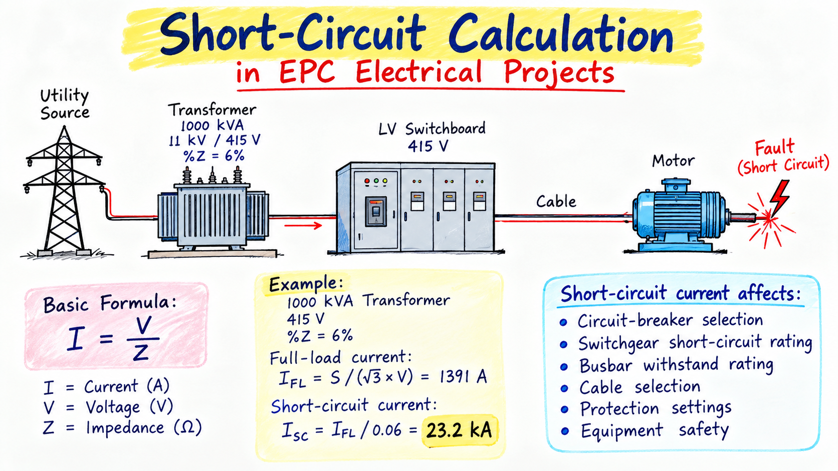
Short-Circuit Calculation in EPC Electrical Projects
Focus Keyword: Short-Circuit Calculation
Introduction
In Lesson 16, we learned about voltage drop.
Now we move to another calculation that is extremely important in EPC electrical design:
If a short circuit occurs at a particular point in the electrical system, how much fault current will flow?
This is the basic question behind a short-circuit calculation.
The answer affects:
- Circuit-breaker selection
- Switchgear short-circuit rating
- Busbar withstand rating
- Cable selection
- Protection settings
- Equipment safety
- Electrical studies
✍️ Handwritten Note
        FAULT OCCURS
             ↓
      SYSTEM IMPEDANCE
             ↓
        FAULT CURRENT
             ↓
      PROTECTION OPERATES
             ↓
      BREAKER INTERRUPTS
             ↓
          SAFE SYSTEM
The simple idea is:
Fault → High Current → Protection → Breaker Trips
1. What Is a Short Circuit?
A short circuit is an abnormal electrical connection that creates a very low-impedance path for current.
Under normal conditions:
SOURCE ───────────── LOAD
Current flows through the intended load.
During a fault:
SOURCE ───────────── LOAD
   │
   │
   └────────── X
             FAULT
Because the fault impedance can be very low, the current can become extremely high.
✍️ Think Like an Electrical Designer
Low impedance = high fault current
High impedance = low fault current
This one concept is the foundation of short-circuit calculations.
2. Why Do EPC Engineers Calculate Short-Circuit Current?
Imagine a transformer supplying an LV switchboard:
       TRANSFORMER
        1000 kVA
            │
            ▼
      LV SWITCHBOARD
            │
       ┌────┼────┐
       ↓    ↓    ↓
      MCC   DB  MOTOR
Suppose the calculated fault current at the switchboard is approximately:
23 kA
You cannot simply install a breaker with an interrupting capability of 10 kA if the applicable prospective fault current exceeds that rating.
Therefore:
Short-circuit calculation is directly connected to switchgear selection.
✍️ Handwritten Engineering Rule
CALCULATED FAULT LEVEL
          ↓
   CHECK BREAKER
SHORT-CIRCUIT RATING
          ↓
   CHECK SWITCHGEAR
          ↓
   CHECK BUSBAR
          ↓
   CHECK CABLE
This is why short-circuit studies are an important part of EPC electrical design.
3. The Main Concept — Ohm’s Law
The basic relationship is:
I = V / Z
Where:
- I = Current
- V = Voltage
- Z = Impedance
For a short circuit:
Fault Current
     =
System Voltage
     /
System Impedance
Therefore:
Lower impedance → Higher fault current
and:
Higher impedance → Lower fault current
✍️ Remember This
       IMPEDANCE ↓
            ↓
      CURRENT ↑↑↑

       IMPEDANCE ↑
            ↓
      CURRENT ↓
If you understand this relationship, you already understand the most important basic idea behind short-circuit calculation.
4. What Is Impedance?
Impedance is the total opposition to AC current.
It contains:
             IMPEDANCE
                 │
          ┌──────┴──────┐
          ↓             ↓
     RESISTANCE      REACTANCE
          R              X
In simplified form:
Z = √(R² + X²)
In an actual short-circuit study, several components can contribute impedance.
For example:
- Utility/source
- Transformer
- Cables
- Busbars
- Motors
- Generators
✍️ Practical View
UTILITY
   ↓
TRANSFORMER
   ↓
BUSBAR
   ↓
CABLE
   ↓
FAULT

Every component in the path
can affect the available fault current.
5. Transformer Impedance
One of the most important values on a transformer datasheet is:
Percentage impedance (%Z)
You learned about transformer impedance in Lesson 11.
Now you can see why that value becomes very important during a short-circuit calculation.
For example:
Transformer
1000 kVA
11 / 0.415 kV
%Z = 6%
The 6% impedance helps determine how much fault current the transformer can deliver at its terminals under the simplified calculation.
6. Why Does Transformer %Z Matter?
Consider:
1000 kVA Transformer
11 kV / 415 V
%Z = 6%
A lower transformer impedance generally allows a higher short-circuit current to flow at its terminals.
A higher transformer impedance generally limits the fault current more.
Therefore:
Transformer impedance has a direct effect on available fault current.
✍️ Handwritten Concept
TRANSFORMER %Z

     LOWER %Z
        ↓
   MORE FAULT CURRENT

     HIGHER %Z
        ↓
   LESS FAULT CURRENT
This becomes important when selecting the downstream switchgear.
7. Calculate Transformer Full-Load Current
Before calculating the simplified short-circuit current, first calculate the transformer’s LV full-load current.
For a three-phase transformer:
I_FL = S / (√3 × V)
Where:
- S = Transformer apparent power in VA
- V = Secondary line voltage
For:
S = 1000 kVA
V = 415 V
Therefore:
I_FL = 1,000,000
       ─────────────
       1.732 × 415
Approximately:
I_FL ≈ 1391 A
So:
1000 kVA Transformer
        ↓
      415 V
        ↓
Full-load current
        ↓
     ≈ 1391 A
8. Calculate Short-Circuit Current Using %Z
For a simplified transformer-limited fault calculation:
I_sc ≈ I_FL / Z_pu
The transformer impedance is:
%Z = 6%
Convert percentage into per-unit:
Z_pu = 6 / 100

Z_pu = 0.06
Therefore:
I_sc = 1391 / 0.06
Approximately:
I_sc ≈ 23,183 A
or:
I_sc ≈ 23.2 kA
✍️ Handwritten Calculation
1000 kVA TX
415 V
6% Z

        ↓

FLC ≈ 1391 A

        ↓

Z = 0.06 pu

        ↓

1391 / 0.06

        ↓

≈ 23.2 kA
So our simplified transformer-limited result is:
⚡ Short-Circuit Current ≈ 23.2 kA
9. Understand What Just Happened
We started with:
1000 kVA Transformer
        ↓
      415 V
        ↓
 Full-load current
        ↓
     1391 A
Then:
Transformer %Z
      ↓
      6%
      ↓
   0.06 pu
Then:
1391 / 0.06
      ↓
   ≈23.2 kA
This is why transformer impedance is so important when selecting LV switchgear.
10. Why Can’t We Stop Here?
This is very important.
23.2 kA is a simplified transformer-limited calculation.
A real EPC short-circuit study may need to consider the complete electrical network.
For example:
UTILITY
   │
   ↓
TRANSFORMER
   │
   ↓
SWITCHBOARD
   │
 ┌─┼────────┐
 ↓ ↓        ↓
CABLE MOTOR  OTHER
            SOURCES
The actual fault current depends on the impedance of the complete system and applicable study assumptions.
11. Source Impedance
The utility or generator supplying the transformer also has impedance.
A more realistic system can look like:
UTILITY
   │
   ↓
SOURCE IMPEDANCE
   │
   ↓
TRANSFORMER
   │
   ↓
TRANSFORMER IMPEDANCE
   │
   ↓
BUSBAR
   │
   ↓
CABLE IMPEDANCE
   │
   X
  FAULT
Every impedance in the fault path affects the available short-circuit current.
✍️ Engineering Thinking
Don’t look only at the transformer.
Ask:
What is connected between the source and the fault?
Every relevant impedance matters.
12. Cable Impedance
Suppose a fault occurs far away from the transformer.
TRANSFORMER
     │
     │
     └──────── LONG CABLE ───────── X
                                  FAULT
The cable has impedance.
Therefore:
Cable length ↑
      ↓
Cable impedance ↑
      ↓
Fault current ↓
This means the fault current at the far end of a long feeder can be significantly different from the fault current directly at the transformer bus.
13. Fault at Transformer Bus vs Far-End Fault
Consider:
          TRANSFORMER
               │
               ▼
            LV BUS
               │
               │
          200 m CABLE
               │
               ▼
             MOTOR
Point A — LV Bus
Transformer → Fault
There is relatively little downstream impedance.
Point B — Motor End
Transformer → Cable → Fault
The cable adds impedance.
Therefore:
Fault current generally decreases as you move farther away from the source through additional impedance.
✍️ Simple Sketch
SOURCE
  │
  │  HIGHER FAULT CURRENT
  ↓
  ●  POINT A
  │
  │  CABLE IMPEDANCE
  │
  ↓
  ●  POINT B
     LOWER FAULT CURRENT
14. Why Does the Breaker Rating Matter?
Suppose our calculated prospective fault current is:
23 kA
Now imagine a breaker with a suitable interrupting rating of:
25 kA
That may be adequate if the applicable fault-study results and breaker rating definitions confirm it.
But a:
10 kA
rating would not be adequate for a 23 kA prospective fault current.
Therefore:
CALCULATED FAULT LEVEL
          ↓
BREAKER SHORT-CIRCUIT
RATING
must be checked together.
15. Continuous Current vs Short-Circuit Rating
This is one of the most important concepts in switchgear selection.
Imagine a breaker marked:
1600 A, 25 kA
These are two different things.
1600 A
This relates to the breaker’s continuous current rating under specified conditions.
25 kA
This relates to its applicable short-circuit interrupting capability/rating under the specified standard and conditions.
✍️ Handwritten Reminder
1600 A
   ↓
CONTINUOUS CURRENT

25 kA
   ↓
SHORT-CIRCUIT RATING
Therefore:
1600 A does not mean the breaker can interrupt a 1600 A fault.
And:
25 kA does not mean the breaker continuously carries 25 kA.
Keep these two concepts separate.
16. Busbar Short-Circuit Withstand
The switchboard busbar also needs to withstand the fault conditions for the specified duration.
For example, a switchboard may have a short-time withstand rating such as:
25 kA for 1 second
The exact rating and terminology depend on the applicable standard and equipment design.
Conceptually:
FAULT
  ↓
HIGH CURRENT
  ↓
THERMAL + MECHANICAL STRESS
  ↓
BUSBAR MUST WITHSTAND IT
Therefore, short-circuit studies affect not only breakers but also the switchboard busbar design.
17. Cable Short-Circuit Withstand
Remember Lesson 13?
We discussed:
S ≥ I√t / k
The short-circuit current and fault-clearing time affect the conductor’s thermal stress.
Therefore:
SHORT-CIRCUIT STUDY
        ↓
   FAULT CURRENT
        ↓
     CABLE CHECK
        ↓
BREAKER CLEARING TIME
Again, the lessons are connected.
This is one of the most important things to understand when learning EPC electrical design:
One calculation is rarely isolated from another.
18. Motor Contribution to Fault Current
Industrial plants can contain many motors.
During certain fault conditions, motors can contribute current to the fault for a short period.
For example:
             UTILITY
                │
           TRANSFORMER
                │
               BUS
          ┌─────┼─────┐
          ↓     ↓     ↓
       MOTOR 1 MOTOR 2 MOTOR 3
                    │
                  FAULT
Therefore, a detailed short-circuit study may include contributions from:
- Utility
- Transformers
- Generators
- Motors
The actual contribution depends on the system and study method.
19. Generator Contribution
Generators can also be significant sources of fault current.
For example:
UTILITY ─────────┐
                 │
                 ▼
              BUSBAR
                 ▲
                 │
             GENERATOR
If the generator is connected during the fault condition being studied, it can contribute to the fault current.
Therefore, emergency and standby operating modes can affect the short-circuit study.
20. Different Fault Types
A short-circuit study may consider different fault types.
1. Three-Phase Fault
R ───┐
Y ───┼── X
B ───┘
This is a balanced fault.
2. Line-to-Ground Fault
PHASE
  │
  X
  │
GROUND
3. Line-to-Line Fault
R ─── X ─── Y
4. Double-Line-to-Ground Fault
Two phases are involved with ground.
Different fault types can produce different fault-current magnitudes.
21. Why Is Three-Phase Fault Important?
For many initial switchgear fault-level checks, the three-phase fault is an important calculation.
It helps engineers understand the prospective short-circuit level at a bus.
For example:
       415 V BUS
          │
          │
          X
        FAULT
The calculated fault level can then be compared with:
- Breaker interrupting capability
- Switchgear short-circuit rating
- Busbar withstand
- Other equipment ratings
22. Short-Circuit Study in an EPC Project
A practical study may look like:
INPUT DATA
    ↓
UTILITY FAULT LEVEL
    ↓
TRANSFORMER DATA
    ↓
GENERATOR DATA
    ↓
MOTOR DATA
    ↓
CABLE DATA
    ↓
NETWORK MODEL
    ↓
SHORT-CIRCUIT CALCULATION
    ↓
FAULT CURRENT AT EACH BUS
    ↓
EQUIPMENT RATING CHECK
    ↓
PROTECTION STUDY
For larger projects, this is usually performed using electrical-system study software.
23. Example Electrical Network
Consider:
                 UTILITY
                    │
                  11 kV
                    │
                   VCB
                    │
                11 kV BUS
                    │
              1000 kVA TX
              11 / 0.415 kV
                    │
                   ACB
                    │
                415 V BUS
              ═════════════
                 │       │
                 │       │
                MCC      DB
                 │
               MOTORS
A short-circuit study can determine the fault level at:
- 11 kV bus
- Transformer secondary
- 415 V main bus
- MCC bus
- Motor feeder
- Other distribution points
✍️ Important EPC Concept
ONE PLANT
   ↓
MANY BUSES
   ↓
DIFFERENT FAULT LEVELS
Don’t assume that one fault-current value applies everywhere.
24. Short-Circuit Current and Protection
Now connect this to protection.
FAULT
  ↓
HIGH CURRENT
  ↓
CT
  ↓
PROTECTION RELAY
  ↓
TRIP SIGNAL
  ↓
CIRCUIT BREAKER
  ↓
FAULT CLEARED
The protection system must operate quickly enough to limit equipment damage and meet the project’s protection requirements.
Therefore:
Short-circuit calculation and protection coordination are closely connected.
25. Short-Circuit Current and Transformer Selection
Remember Lesson 11?
We discussed transformer impedance.
Now you can see why it matters.
Consider two transformers:
TRANSFORMER A
1000 kVA
Z = 4%
and:
TRANSFORMER B
1000 kVA
Z = 8%
For the same transformer rating and voltage, the lower-impedance transformer generally produces a higher transformer-limited fault current at its terminals than the higher-impedance transformer.
✍️ Connection
TRANSFORMER IMPEDANCE
          ↓
     FAULT CURRENT
          ↓
   SWITCHGEAR RATING
          ↓
      PROTECTION
This is why transformer selection and switchgear selection cannot be treated as completely independent decisions.
26. Short-Circuit Calculation — Simple Formula
For a three-phase system, the simplified relationship is:
Isc = Ssc / (√3 × V)
Where:
- Isc = short-circuit current
- Ssc = short-circuit apparent power
- V = system line voltage
For example, if the short-circuit level is:
16 MVA
at:
415 V
then:
Isc = 16,000,000
      ─────────────
      1.732 × 415
Approximately:
22.3 kA
This is another way of expressing the fault level.
27. Fault Level in MVA
Engineers may express short-circuit strength as:
Short-circuit level = MVA
or:
Short-circuit current = kA
They are related.
For a three-phase system:
Ssc = √3 × V × Isc
Therefore:
MVA = √3 × kV × kA
✍️ Easy Conversion
     kA
      ↕
SHORT-CIRCUIT
      ↕
     MVA
This relationship is very useful when reading electrical studies.
28. Example: Convert kA to MVA
Suppose:
Voltage = 415 V
        = 0.415 kV

Fault Current = 25 kA
Then:
Ssc = √3 × 0.415 × 25
Approximately:
17.97 MVA
So:
25 kA at 415 V ≈ 18 MVA short-circuit level
29. Short-Circuit Study Is Not Just One Number
A common beginner mistake is to think:
“The plant fault level is 25 kA.”
In reality, the fault level can vary from one location to another.
For example:
11 kV BUS
   ↓
Fault Level = X kA

415 V MAIN BUS
   ↓
Fault Level = Y kA

MCC BUS
   ↓
Fault Level = Z kA

MOTOR TERMINAL
   ↓
Fault Level = W kA
The location matters.
✍️ Remember
SOURCE
  ↓
BUS
  ↓
FEEDER
  ↓
MCC
  ↓
MOTOR

Fault level changes
as the electrical path changes.
30. Minimum and Maximum Fault Current
Protection studies can require consideration of different fault-current conditions.
Maximum Fault Current
Important for:
- Breaker interrupting capability
- Busbar withstand
- Equipment ratings
Minimum Fault Current
Can be important for:
- Protection sensitivity
- Relay operation
- Fault detection
- Coordination
Therefore, a study may need to evaluate more than just the maximum fault current.
31. Short-Circuit Calculation Workflow
Remember this sequence:
SOURCE DATA
     ↓
TRANSFORMER DATA
     ↓
GENERATOR DATA
     ↓
MOTOR DATA
     ↓
CABLE DATA
     ↓
SYSTEM IMPEDANCE
     ↓
FAULT CURRENT
     ↓
FAULT LEVEL
     ↓
EQUIPMENT RATING CHECK
     ↓
PROTECTION STUDY
✍️ EPC Designer’s View
When you receive a short-circuit study, don’t just look at the final kA value.
Try to understand:
Where was the fault calculated?
What sources were included?
What system configuration was considered?
What equipment rating needs to be checked against it?
🧠 What You Should Know After Lesson 17
You should now understand:
1. Short circuit
A short circuit creates a very high current because the fault impedance is low.
2. Basic relationship
I = V / Z
3. Transformer impedance
Transformer % impedance has a major effect on fault current.
4. Example
A 1000 kVA, 415 V transformer with 6% impedance gives a simplified transformer-limited fault current of approximately:
23.2 kA
5. Cable impedance
Fault current generally decreases as additional impedance is added between the source and fault.
6. Breaker ratings
Breaker continuous-current rating and short-circuit interrupting capability are different ratings.
7. Busbar and cable
Busbars and cables also need appropriate short-circuit withstand capability.
8. Other sources
Generators and motors can contribute to fault current in applicable operating conditions.
9. Fault level
Fault level can be expressed in kA or MVA.
10. Location
The fault current must be studied at different locations in the electrical network.
🎯 EPC Engineer Exercise
Try these before moving to Lesson 18.
Question 1
A transformer is:
- 1000 kVA
- 415 V
- 6% impedance
Calculate its approximate full-load current.
Then calculate the simplified transformer-limited short-circuit current.
Question 2
What happens to the calculated fault current if transformer impedance changes from:
6% → 8%?
Does the transformer-limited fault current increase or decrease?
Question 3
A switchboard has:
1600 A, 25 kA
What does 1600 A represent?
What does 25 kA represent?
Question 4
Why is the fault current at the transformer secondary bus generally different from the fault current at the end of a long cable?
Question 5
Convert:
25 kA at 415 V
into approximate short-circuit MVA.
Use:
Ssc = √3 × V × I
Question 6
Name four possible sources that may contribute to short-circuit current in an industrial plant.
🚀 Your EPC Learning Path
You now have:
LESSON 13
Cable Sizing
     ↓
LESSON 14
Motor Electrical Design
     ↓
LESSON 15
Practical SLD Reading
     ↓
LESSON 16
Voltage Drop
     ↓
LESSON 17
SHORT-CIRCUIT CALCULATION
And now comes a very important connection.
⚡ Lesson 18 — Protection & Coordination
We know:
FAULT
  ↓
SHORT-CIRCUIT CURRENT
  ↓
PROTECTION DEVICE
  ↓
BREAKER TRIPS
But there is another important question:
Which breaker should trip first?
For example:
TRANSFORMER
     ↓
  MAIN ACB
     ↓
     MCC
     ↓
    MCCB
     ↓
    MOTOR
If a fault occurs at the motor, we generally want the motor feeder protection to clear the local fault without unnecessarily tripping the upstream main breaker, where the protection philosophy and system design call for selectivity.
That’s the next major concept:
⚡ Protection coordination and selectivity