
Understanding the Single Line Diagram (SLD)

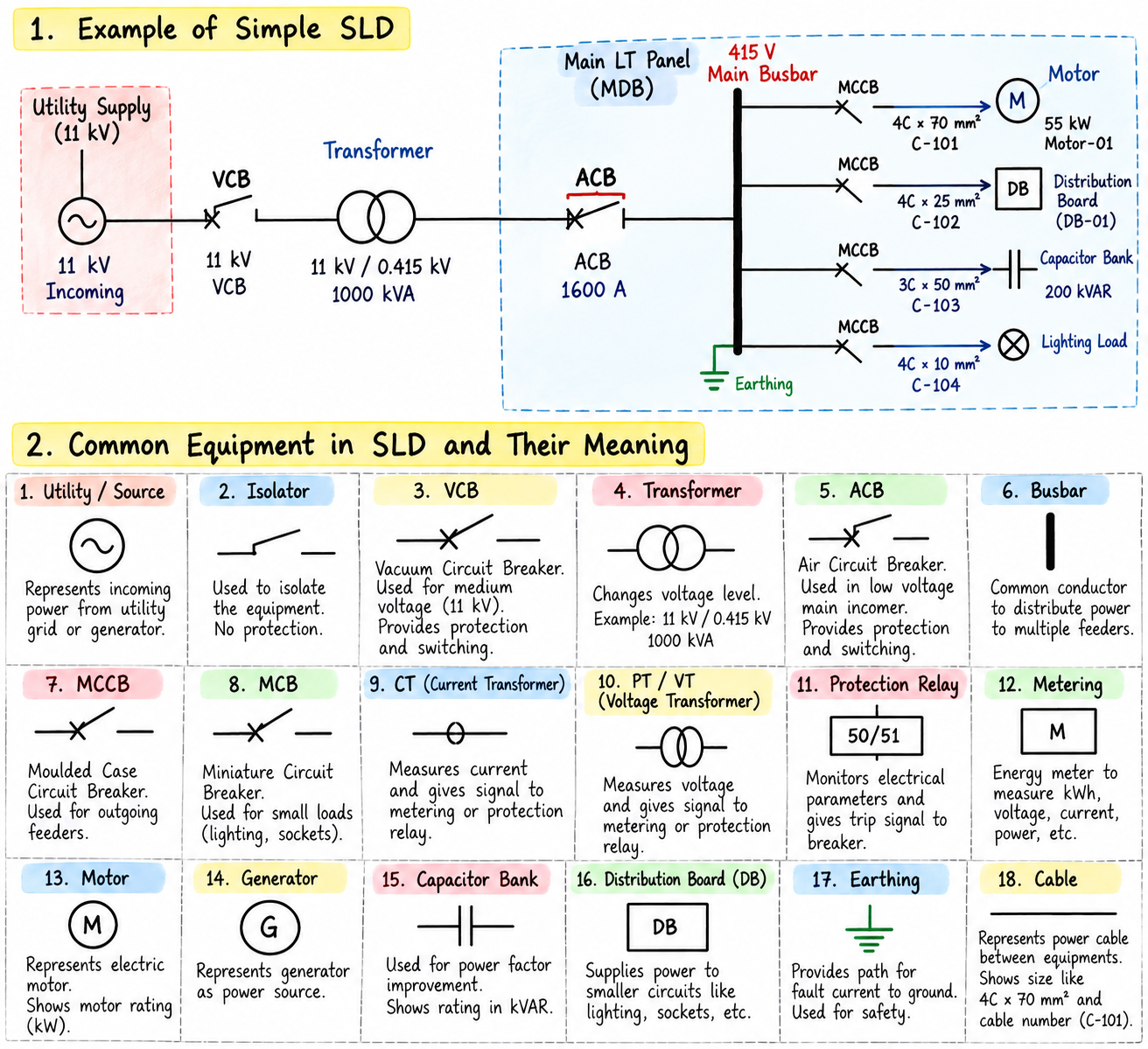
Table of Contents
If you work in Electrical EPC, you will see Single Line Diagrams (SLDs) everywhere.
Electrical EPC Design Course — Beginner to Professional Level
The SLD is one of the most important drawings you will encounter as an electrical engineer. It provides a simplified view of the electrical system and allows you to understand how power flows through the plant.
Eventually, when you look at an SLD, you should be able to answer four basic questions:
Where does the power come from? → Where does it go? → What equipment is connected? → How is it protected?
You should also be able to understand:
What happens when an electrical fault occurs?
Don’t worry if an SLD looks confusing at first. In this lesson, we’ll build it step by step.
1. What is Single Line Diagram (SLD)?
SLD = Single Line Diagram.
A Single Line Diagram is a simplified representation of a three-phase electrical system using a single line.
But why only one line?
In a three-phase electrical system, there are three phases. Drawing all three phases throughout a large electrical system would make the drawing unnecessarily complicated.
For example, instead of showing:
Phase R ─────────────────
Phase Y ─────────────────
Phase B ─────────────────
an SLD represents the three-phase circuit using a simplified single line:
─────────────────
That single line represents the three-phase electrical connection.
Important
An SLD is not an exact physical layout of the equipment.
It is a simplified engineering representation used to communicate:
- Power flow
- Equipment connections
- Distribution arrangement
- Protection
- Voltage levels
- Electrical sources and loads
2. Why Is the Single Line Diagram (SLD) So Important?
Think of an SLD as the map of the electrical system.
For example:
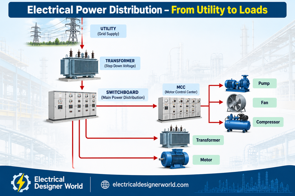
Even this simple diagram tells us something important:
Where the power enters → how the voltage changes → where power is distributed → what loads are supplied.
This ability to trace the power path is one of the most important skills for an EPC electrical engineer.
3. Let’s Build Our First Single Line Diagram (SLD)
Instead of trying to understand a complicated industrial SLD immediately, let’s start with the simplest possible electrical system.
       SOURCE
          │
          ▼
        LOAD
That’s it.
Now let’s add protection.
       SOURCE
          │
          ▼
       BREAKER
          │
          ▼
        LOAD
Now we have our first basic electrical power path:
Source → Breaker → Load
The circuit breaker provides switching and, as part of the protection system, can interrupt fault current when required.
This simple concept appears repeatedly in larger electrical systems.
4. Add a Transformer
Now suppose:
- Incoming supply = 11 kV
- Motor operating voltage = 415 V
We need a transformer to change the voltage level.
A simplified SLD becomes:
             11 kV
               │
              CB
               │
               ▼
        ┌─────────────┐
        │ TRANSFORMER │
        │ 11/0.415 kV │
        └─────────────┘
               │
             415 V
               │
               ▼
             MOTOR
Now we have a basic distribution system:
11 kV → Circuit Breaker → Transformer → 415 V → Motor
This is the foundation for understanding larger industrial SLDs.
5. Understanding the Busbar
Now imagine that we have many electrical loads.
We don’t want to connect every load individually to the transformer terminal.
Instead, we use a common electrical connection called a:
Busbar
Think of a busbar as a common highway for electrical power.
For example:
                  TRANSFORMER
                       │
                       ▼
              =================
                   415 V BUS
              =================
                 │      │      │
                 ▼      ▼      ▼
               MCC-1   DB-1   MCC-2
Electrical power enters the busbar and can then be distributed to multiple outgoing feeders.
In simple terms:
Busbar = Common electrical connection from which multiple circuits can be supplied.
Busbars are fundamental components of switchboards and switchgear assemblies.
6. What Is an Incomer?
The circuit that brings electrical power into a switchboard or bus is generally called an:
Incomer
For example:
              TRANSFORMER
                   │
                   ▼
              [ INCOMER ]
                   │
                   ▼
           =================
                  BUS
           =================
The incomer is therefore the incoming circuit that supplies the bus.
So when someone says:
“Check the incomer rating.”
they are referring to the incoming feeder/circuit supplying that board or bus.
7. What Is an Outgoing Feeder?
A circuit leaving the bus and supplying another piece of equipment or downstream system is generally called an:
Outgoing Feeder
For example:
                  INCOMER
                     │
                     ▼
              ===============
                    BUS
              ===============
                │      │      │
                ▼      ▼      ▼
             Feeder  Feeder  Feeder
                │      │      │
                ▼      ▼      ▼
              Motor     DB     MCC
The easiest way to remember it is:
Incomer
Power coming in
Outgoing Feeder
Power going out
This terminology is extremely common in EPC electrical engineering.
8. Circuit Breaker (CB)
You will see CB everywhere on electrical drawings.
CB = Circuit Breaker
A circuit breaker is used to:
- Switch a circuit
- Interrupt fault current
- Protect electrical equipment when used with the appropriate protection system
For example:
       BUS
        │
        ▼
      [ CB ]
        │
        ▼
      MOTOR
If a serious electrical fault occurs, the protection system detects the fault and commands the circuit breaker to open.
The breaker then disconnects the affected circuit and helps isolate the fault.
9. CT — Current Transformer
Now we come to an important component used for protection and measurement.
Suppose the current in a large feeder is:
1,000 A
We generally don’t connect a protection relay directly to a 1,000 A primary conductor.
Instead, we use a:
CT = Current Transformer
For example:
1000/1 A CT
Conceptually:
       1000 A PRIMARY
              │
              ▼
             CT
              │
              ▼
        1 A SECONDARY
              │
              ▼
       PROTECTION RELAY
The CT provides a scaled current signal suitable for:
- Protection
- Metering
- Monitoring
For example, a 1000/1 A CT ideally produces approximately 1 A secondary current when 1000 A flows in the primary, subject to the CT’s operating characteristics.
We will later learn how CT ratios and CT classes are selected.
10. PT / VT — Voltage Transformer
Just as we need to measure high current safely, we also need a practical way to measure high voltage.
We can use a:
PT = Potential Transformer
or:
VT = Voltage Transformer
For example:
11,000 / 110 V
Conceptually:
             11 kV
               │
               ▼
            PT / VT
               │
               ▼
              110 V
               │
            ┌──┴──┐
            ▼     ▼
          Meter  Protection
The PT/VT provides a scaled voltage suitable for measurement and protection equipment.
11. Protection Relay
Now let’s put the CT, relay, and circuit breaker together.
A simplified protection chain is:
             POWER CIRCUIT
                   │
                   ▼
                  CT
                   │
                   ▼
            PROTECTION RELAY
                   │
             TRIP SIGNAL
                   │
                   ▼
            CIRCUIT BREAKER
Suppose there is an electrical fault.
The sequence is:
Fault
  ↓
Abnormal / High Current
  ↓
CT
  ↓
Protection Relay
  ↓
Trip Signal
  ↓
Circuit Breaker Opens
  ↓
Fault Isolated
This is one of the most fundamental concepts in electrical protection.
The basic idea
CT senses → Relay decides → Breaker trips
The actual protection logic can be much more sophisticated, but this is the fundamental concept you should understand first.
12. Let’s Build a Realistic Single Line Diagram (SLD)
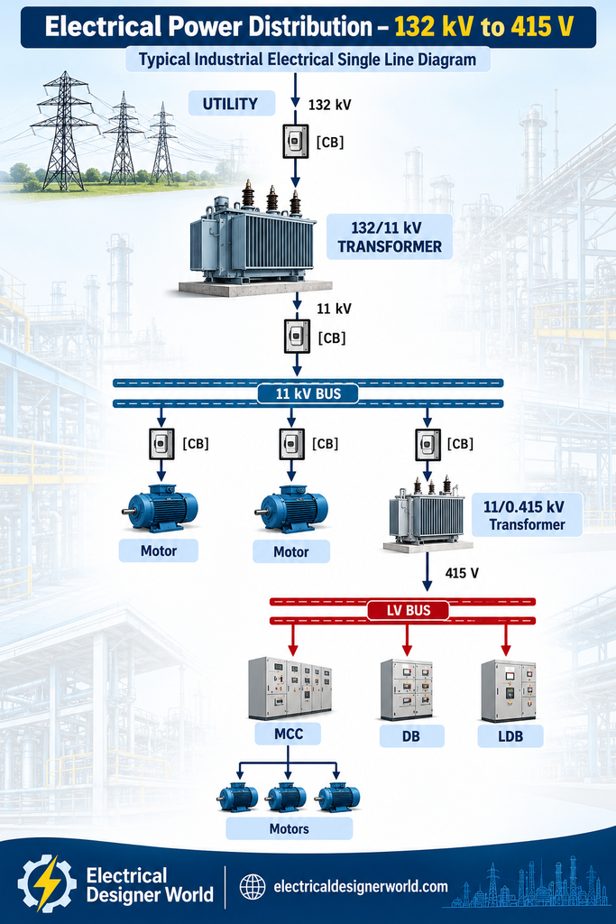
Now let’s combine everything we’ve learned so far.
Now we can actually trace the power path through the system.
13. Let’s Trace One Motor
Suppose motor M-101 is connected directly to the 11 kV bus.
Follow the power path:
UTILITY
   ↓
132 kV
   ↓
132/11 kV TRANSFORMER
   ↓
11 kV BUS
   ↓
CIRCUIT BREAKER
   ↓
CABLE
   ↓
MOTOR M-101
Therefore, if someone asks:
“How is M-101 supplied?”
you should be able to trace its supply path on the SLD.
This is a basic but extremely important skill.
14. What Happens During an Electrical Fault?
Now imagine the motor develops a short circuit.
Conceptually:
11 kV BUS
    │
   CB
    │
  Cable
    │
  Motor
    │
  ⚠️ FAULT
The fault can cause a large current.
The protection system then operates.
Fault
  ↓
High / Abnormal Current
  ↓
CT
  ↓
Protection Relay
  ↓
Trip Signal
  ↓
Breaker Opens
  ↓
Fault Isolated
This simple chain is fundamental electrical engineering.
As you progress, you will learn that different protection functions detect different types of abnormal conditions.
15. Bus Coupler / Bus Section
Here’s another term you will encounter frequently on industrial SLDs:
Bus Coupler
Suppose a bus is divided into two sections:
        SECTION-A                 SECTION-B
================================================
        11 kV BUS                 11 kV BUS
================================================
                 │
                 │
            BUS COUPLER
A bus coupler can connect the two bus sections when required, depending on the operating philosophy.
Why divide a bus into sections?
Possible reasons include:
- Reliability
- Maintenance
- Fault isolation
- Load management
- Redundancy
The exact operating philosophy depends on the project.
The bus coupler may be normally open or normally closed depending on the system design and operating requirements.
16. Why Do EPC Engineers Spend So Much Time on SLDs?
Because the SLD becomes the backbone of many electrical engineering activities.
From the SLD, engineers can understand or establish:
- Number of transformers
- Switchboards
- Feeders
- Breakers
- Bus sections
- Motors
- Distribution levels
- Protection arrangements
The SLD also provides an important basis for engineering activities such as:
Load Flow
Determines how power and current flow through the electrical network under defined operating conditions.
Short-Circuit Study
Determines fault currents and helps verify equipment ratings and protection requirements.
Protection Coordination
Helps establish how protective devices should operate selectively during faults.
Cable Sizing
Uses system configuration and load information to support cable selection.
Equipment Specifications
Provides the electrical system requirements needed for equipment specifications.
Procurement
Electrical equipment must ultimately be purchased according to the approved design requirements.
Construction
The approved electrical design becomes an important reference for installation and construction activities.
Therefore:
The SLD is not just a drawing. It is one of the key engineering documents connecting different stages of an EPC electrical project.
🧠 Your Mental Checklist When Looking at an SLD
Whenever someone gives you an SLD, don’t just look at the symbols.
Ask yourself these questions.
① Where is the source?
Where does the power enter the system?
② What is the voltage?
132 kV? 33 kV? 11 kV? 415 V?
③ Where are the transformers?
Where is the voltage being changed?
④ Where are the buses?
Where is electrical power being distributed?
⑤ Where are the incomers?
How does power enter each board?
⑥ Where are the outgoing feeders?
What does each feeder supply?
⑦ Where are the breakers?
What circuits can be switched and protected?
⑧ Where are the CTs and VTs?
How are measurement and protection signals obtained?
⑨ How does power reach the load?
Can you trace the complete power path?
If you can answer these questions, you are already beginning to read an SLD like an electrical engineer.
🎯 Mini Exercise
Consider this simplified system:
             11 kV SOURCE
                   │
                  CB
                   │
                   ▼
                11 kV BUS
                 │      │
                CB      CB
                 │      │
                 ▼      ▼
               Motor  Transformer
                         │
                       415 V
                         │
                         ▼
                       LV BUS
                         │
                        MCC
                         │
                         ▼
                       Motor
Try answering these questions without looking back at the lesson:
1. What is the source voltage?
2. What is the voltage at the LV bus?
3. What is the purpose of the transformer?
4. What is the purpose of the circuit breaker?
5. What is the 11 kV bus doing?
6. Trace the power path from the 11 kV source to the motor connected to the MCC.
Don’t worry about memorizing every SLD symbol yet.
The goal at this stage is to develop the ability to follow the power flow.
Reference Standards for Electrical Single Line Diagrams
When preparing and interpreting a Single Line Diagram (SLD), it is important to understand the relevant electrical standards and safety requirements. The International Electrotechnical Commission (IEC) publishes standards covering electrical installations, equipment selection, wiring systems, and electrical safety. For further technical reference, readers can explore the IEC 60364-1 standard for low-voltage electrical installations and the IEC 60364-5-52 standard for wiring systems. These resources help electrical engineering students and professionals develop a better understanding of electrical installation principles and design requirements. Always follow the applicable project specifications and relevant local standards when preparing electrical drawings.
🚀 What Comes Next?
So far, we have learned:
Electrical Design Basis → Electrical Load List → Power Distribution System → Single Line Diagram
Now it is time to understand the major electrical equipment that appears on these systems.
Lesson 7 — Electrical Equipment: Transformer, Switchgear, MCC & PCC
In the next lesson, we will take each major piece of electrical equipment and understand:
- What it does
- Why it is required
- Important ratings
- Basic construction
- How it is connected
- What an EPC engineer needs to consider when selecting it
We will start turning the symbols and blocks we see on an SLD into real electrical equipment that you can understand and work with. ⚡🔥