
Protection & Coordination in EPC Electrical Projects
In Lesson 17, we calculated short-circuit current.
Now comes the next important question:
When a fault occurs, which protective device should operate, and how quickly?
This is the purpose of protection and coordination.
Consider a simple electrical system:
        TRANSFORMER
             │
             ↓
          MAIN ACB
             │
             ↓
           BUSBAR
             │
             ↓
            MCC
             │
             ↓
           MCCB
             │
             ↓
           CABLE
             │
             ↓
           MOTOR
If a fault occurs near the motor, we generally want the motor feeder protection to clear that local fault without unnecessarily disconnecting the upstream system, where the project protection philosophy calls for selectivity.
This concept is called protection coordination or selectivity.
1. What Is Electrical Protection?
Electrical protection is the system used to detect abnormal conditions and disconnect the affected part of the electrical network.
Abnormal conditions can include:
- Short circuit
- Overload
- Earth fault
- Overcurrent
- Undervoltage
- Overvoltage
- Other equipment-specific abnormal conditions
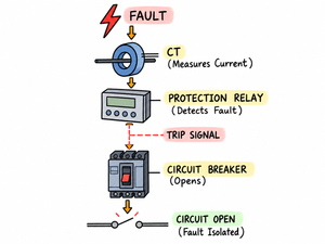
A simple protection sequence is:
       ⚡ ABNORMAL CONDITION
                 ↓
              CT / VT
                 ↓
         PROTECTION RELAY
                 ↓
            TRIP SIGNAL
                 ↓
         CIRCUIT BREAKER
                 ↓
           CIRCUIT OPEN
The important point is that the protection system should isolate the fault while keeping the healthy part of the electrical system energized where possible.
Think about it simply:
⚡ FAULT
   ↓
👀 RELAY DETECTS
   ↓
📢 TRIP COMMAND
   ↓
🔴 BREAKER OPENS
   ↓
✅ FAULT ISOLATED
The relay detects the abnormal condition, while the circuit breaker performs the actual interruption of the power circuit.
2. Why Do We Need Protection?
Imagine that a motor feeder develops a short circuit.
TRANSFORMER
     │
     ↓
    ACB
     │
     ↓
   BUSBAR
     │
     ↓
   MCCB
     │
     ↓
   CABLE
     │
     ⚡
    FAULT
     │
     ↓
   MOTOR
If nothing operates after the fault:
FAULT
  ↓
VERY HIGH CURRENT
  ↓
CABLE HEATING
  ↓
EQUIPMENT STRESS
  ↓
POSSIBLE DAMAGE
The purpose of protection is to detect the abnormal condition and disconnect the affected circuit before the fault causes unacceptable damage.
A simple way to remember it:
⚡ FAULT
   ↓
CURRENT ↑↑↑
   ↓
🛡️ PROTECTION
   ↓
🔴 BREAKER TRIP
   ↓
MOTOR ISOLATED
3. Protection Is Not the Same as Coordination
These two concepts are closely related, but they are not the same.
Protection
Protection answers:
Can we detect and clear the fault?
Coordination
Coordination answers:
Which protective device should operate?
For example:
TRANSFORMER
     ↓
  MAIN ACB
     ↓
    MCC
     ↓
   MCCB
     ↓
   MOTOR
If the motor feeder develops a fault, we generally prefer:
⚡ MOTOR FAULT
       ↓
      MCCB
       ↓
     TRIPS
rather than:
⚡ MOTOR FAULT
       ↓
    MAIN ACB
       ↓
     TRIPS
The reason is simple: the MCCB is closer to the fault.
This is the basic idea of selectivity.
4. What Is Selectivity?
Selectivity means arranging protection devices so that the device nearest to the fault operates first, where the protection philosophy and device characteristics permit.
Consider:
          MAIN ACB
              │
              ↓
           BUSBAR
              │
              ↓
             MCC
              │
              ↓
            MCCB
              │
              ↓
            MOTOR
If the motor develops a fault:
        ⚡ MOTOR FAULT
               ↓
             MCCB
               ↓
          MCCB TRIPS
               ↓
        MOTOR ISOLATED
The main ACB can remain closed.
That means other healthy feeders can continue operating.
This is why selectivity is particularly valuable in industrial electrical systems.
5. Why Is This Important in an Industrial Plant?
Imagine an industrial plant with 50 motors.
Suppose Motor 12 develops a fault.
If the main incomer trips:
MOTOR 12 FAULT
       ↓
  MAIN ACB TRIPS
       ↓
 ENTIRE MCC LOSES SUPPLY
       ↓
 MANY HEALTHY MOTORS STOP
A single motor fault has now affected many other loads.
With proper coordination:
MOTOR 12 FAULT
       ↓
MOTOR FEEDER MCCB TRIPS
       ↓
MOTOR 12 ISOLATED
       ↓
OTHER FEEDERS REMAIN ON
The basic objective is:
Isolate the faulty section without unnecessarily disturbing healthy sections.
6. Main Protection Devices
In an industrial LV/MV system, you may encounter several types of protection devices.
ACB — Air Circuit Breaker
ACBs are commonly used for major LV incomers and large feeders.
MCCB — Moulded Case Circuit Breaker
MCCBs are commonly used for LV feeders and distribution circuits.
VCB — Vacuum Circuit Breaker
VCBs are commonly used in medium-voltage systems such as 11 kV.
Protection Relay
A protection relay detects abnormal electrical conditions and initiates breaker operation.
A simple arrangement is:
11 kV
  ↓
 VCB
  ↓
TRANSFORMER
  ↓
415 V
  ↓
 ACB
  ↓
  MCC
  ↓
 MCCB
  ↓
 MOTOR
The actual arrangement depends on the project design and voltage level.
7. Protection Functions
Protection devices can have different protection functions.
| Protection Function | ANSI/IEEE Device Number |
|---|---|
| Overcurrent | 50 / 51 |
| Earth Fault | 50N / 51N |
| Undervoltage | 27 |
| Overvoltage | 59 |
| Underfrequency | 81U |
| Overfrequency | 81O |
You will frequently see these device numbers in protection drawings, relay settings and electrical studies.
A simple memory aid:
50 / 51   → ⚡ OVERCURRENT
50N / 51N → 🌍 EARTH FAULT
27        → ↓ UNDERVOLTAGE
59        → ↑ OVERVOLTAGE
81U       → ↓ UNDERFREQUENCY
81O       → ↑ OVERFREQUENCY
8. Overcurrent Protection
Overcurrent protection operates when the current exceeds the relevant protection threshold according to the device characteristics and settings.
Conceptually:
NORMAL CURRENT
      ↓
PROTECTION REMAINS ON
      ↓
CURRENT BECOMES EXCESSIVE
      ↓
PROTECTION OPERATES
      ↓
BREAKER TRIPS
Overcurrent protection is important for:
- Feeders
- Transformers
- Motors
- Distribution systems
The protection setting must be selected according to the electrical system and equipment requirements.
9. Instantaneous Overcurrent
Instantaneous protection operates very quickly when current exceeds its applicable threshold.
Imagine a circuit normally carrying:
100 A
During a fault, it may experience:
5000 A
NORMAL
100 A
  ↓
🙂 SYSTEM RUNNING

       ⚡

FAULT
5000 A
  ↓
🚨 VERY HIGH CURRENT
The fault current is far above the normal operating current.
Instantaneous protection can operate rapidly depending on the protection setting and device characteristics.
10. Time-Delayed Overcurrent
Not every overcurrent condition should cause an immediate trip.
For example:
SMALL OVERCURRENT
       ↓
   TIME DELAY
       ↓
DOWNSTREAM DEVICE
GETS TIME TO OPERATE
Why?
Because we may want the downstream protective device to clear the fault first.
This is where coordination becomes important.
The downstream device gets an opportunity to operate before the upstream device operates, provided the actual protection characteristics allow this.
11. Example of Coordination
Consider:
        TRANSFORMER
             │
             ↓
          MAIN ACB
             │
             ↓
           BUSBAR
             │
             ↓
            MCC
             │
             ↓
           MCCB
             │
             ↓
           MOTOR
Suppose the motor feeder experiences a moderate overcurrent.
We want the downstream MCCB to have the opportunity to operate first.
Conceptually:
MCCB
 │
 │    OPERATES FIRST
 │
 │
 │
MAIN ACB
 │
 │    OPERATES LATER
 │
 └────────────────────→ CURRENT
The exact operating relationship cannot simply be assumed. Engineers must evaluate the actual time-current characteristics and protection settings of the devices.
12. Time-Current Characteristic — TCC
One of the most important tools in protection coordination is the:
Time-Current Characteristic (TCC)
A TCC shows the relationship between current and operating time.
          OPERATING
             TIME
               ↑
               │\
               │ \
               │  \  DOWNSTREAM
               │   \
               │    \
               │     \ UPSTREAM
               │      \
               └────────────────→
                     CURRENT
The actual curves used in engineering studies are much more detailed.
Engineers use TCC plots to determine whether protection devices coordinate correctly.
A useful way to remember it:
The TCC tells us when each protection device is expected to operate for a particular current.
13. Downstream vs Upstream Protection
Remember this basic arrangement:
SOURCE
  ↓
UPSTREAM DEVICE
  ↓
DOWNSTREAM DEVICE
  ↓
LOAD
The downstream device is electrically closer to the load.
For example:
TRANSFORMER
     ↓
   ACB          ← UPSTREAM
     ↓
   MCC
     ↓
   MCCB         ← DOWNSTREAM
     ↓
   MOTOR
For a motor fault, the MCCB should generally have the first opportunity to clear the fault when selective operation is required and achievable.
14. What Happens If Coordination Is Poor?
Imagine:
MOTOR FAULT ⚡
      ↓
MCCB SHOULD TRIP
But the main ACB and MCCB operate at nearly the same time.
Then:
MOTOR FAULT
     ↓
MCCB + ACB
     ↓
BOTH TRIP
     ↓
MCC LOSES SUPPLY
Now the entire MCC may lose power even though the original fault was only on one motor feeder.
This is an example of poor selectivity.
Compare the two situations:
GOOD COORDINATION 😊

Motor Fault
     ↓
   MCCB
     ↓
Motor isolated
     ↓
Other feeders ON
and:
POOR COORDINATION 😟

Motor Fault
     ↓
MCCB + ACB
     ↓
Both trip
     ↓
MCC affected
15. Protection Coordination Is Not Always Absolute
An important EPC engineering point is:
Perfect selectivity cannot always be achieved for every fault level and every device combination.
The achievable coordination depends on:
- Breaker characteristics
- Protection settings
- Fault level
- Device manufacturer
- Current-limiting behavior
- System configuration
- Project requirements
Therefore:
Coordination must be verified rather than assumed.
This is why protection coordination is an engineering study, not simply a matter of choosing breakers with different current ratings.
16. Short-Circuit Study + Protection Study
Now connect Lesson 17 with Lesson 18.
In Lesson 17, we asked:
How much fault current can flow?
Now we ask:
How should the protection respond to that fault?
The relationship is:
SHORT-CIRCUIT STUDY
        ↓
    FAULT CURRENT
        ↓
 PROTECTION SETTINGS
        ↓
 COORDINATION STUDY
        ↓
 BREAKER OPERATION
So the two studies are closely connected.
A designer should not think of short-circuit calculation and protection coordination as two completely separate subjects.
17. Transformer Protection
Consider a simple transformer arrangement:
       11 kV
         │
        VCB
         │
         ↓
    TRANSFORMER
         │
        ACB
         │
         ↓
       415 V
The transformer may require protection against conditions such as:
- Overcurrent
- Earth fault
- Internal faults
- Overtemperature
- Other transformer-specific abnormal conditions
The exact protection arrangement depends on the transformer type, rating, voltage level and project protection philosophy.
18. Motor Protection
A motor feeder may contain several protection functions.
             MOTOR
               ↑
               │
          PROTECTION
               │
       ┌───────┼───────┐
       ↓       ↓       ↓
   OVERLOAD  SHORT   EARTH
             CIRCUIT  FAULT
Motor protection may need to address:
- Overload
- Short circuit
- Earth fault
- Starting conditions
- Phase-related abnormalities
- Motor-specific protection requirements
The exact protection functions depend on motor size, voltage, criticality and project protection philosophy.
19. Earth-Fault Protection
An earth fault occurs when a live conductor unintentionally contacts earth or an earthed part.
Conceptually:
      PHASE
        │
        │
        ⚡
        │
      EARTH
        🌍
The fault current returns through the grounding path.
Protection detects the abnormal condition and can disconnect the affected circuit.
Earth-fault protection is particularly important in industrial electrical systems.
20. CTs in Protection
Remember:
CT = Current Transformer
The protection relay needs a current signal.
The CT provides a scaled representation of the primary current.
For example:
POWER CIRCUIT
      │
      ↓
     CT
      │
      ↓
PROTECTION RELAY
      │
      ↓
BREAKER TRIP
The CT must be appropriately selected for:
- Ratio
- Accuracy
- Protection class
- Burden
- Fault conditions
- Application
Think of the CT as the relay’s current sensor:
⚡ PRIMARY CURRENT
        ↓
       CT
        ↓
👀 RELAY "SEES" CURRENT
        ↓
🧠 PROTECTION DECISION
21. Relay Settings
A protection relay may have settings such as:
- Pickup current
- Time delay
- Instantaneous threshold
- Earth-fault pickup
- Earth-fault delay
For example:
NORMAL CURRENT
      ↓
NO OPERATION

OVERCURRENT
      ↓
PICKUP REACHED
      ↓
TIMER
      ↓
TRIP
The actual settings must be determined from the system study and protection philosophy rather than simply guessed.
An important point for an EPC designer:
Protection settings are engineering decisions based on the system, not numbers selected randomly.
22. Protection Coordination Example
Let’s take a simple arrangement:
TRANSFORMER
     │
    ACB
     │
     ↓
  PCC BUS
     │
    MCCB
     │
     ↓
   MOTOR
Suppose a fault occurs at the motor.
The protection philosophy may be:
MOTOR FAULT
     ↓
MCCB DETECTS FAULT
     ↓
MCCB TRIPS
     ↓
MOTOR ISOLATED
If the MCCB fails to clear the fault, upstream protection may operate as backup:
MCCB FAILS
     ↓
UPSTREAM ACB
     ↓
   TRIPS
Therefore:
Downstream protection provides primary protection; upstream protection can provide backup protection.
The exact arrangement depends on the protection design.
23. Primary and Backup Protection
Primary Protection
The protection closest to the fault is intended to clear the fault.
Backup Protection
If the primary protection or breaker fails to clear the fault, another protection device operates.
          ⚡ FAULT
             ↓
      PRIMARY PROTECTION
             ↓
         SUCCESS?
        ↙       ↘
      YES        NO
       ↓          ↓
    CLEAR       BACKUP
    FAULT      PROTECTION
                  ↓
                TRIP
This provides another layer of protection for the electrical system.
24. Discrimination
You may hear another term in protection engineering:
Discrimination
In many electrical-protection contexts, discrimination refers to arranging protective devices so the device intended to isolate the fault operates preferentially over upstream devices.
It is closely related to:
Selectivity
For your EPC learning, remember:
SELECTIVITY / DISCRIMINATION
             ↓
      FAULTY SECTION
          ISOLATED
             ↓
     HEALTHY SECTIONS
       REMAIN ENERGIZED
This is the basic idea behind coordinated protection.
25. Protection Coordination and Cable
Remember the cable-sizing concepts from your previous lessons.
The cable must be protected against excessive thermal stress.
So we have:
LOAD
 ↓
CABLE
 ↓
BREAKER
The breaker must be suitable for protecting the cable and load according to the applicable design requirements.
This creates an important engineering relationship:
      CABLE SIZE
           ↕
     BREAKER RATING
           ↕
   PROTECTION SETTING
           ↕
      FAULT CURRENT
These parameters cannot always be selected independently.
A practical EPC designer should therefore think:
📏 CABLE
   ↕
🔴 BREAKER
   ↕
🧠 PROTECTION
   ↕
⚡ FAULT LEVEL
26. Protection Coordination and Transformer
Now connect the concepts from several previous lessons:
TRANSFORMER
     ↓
SHORT-CIRCUIT CURRENT
     ↓
SWITCHGEAR RATING
     ↓
PROTECTION SETTINGS
     ↓
COORDINATION
For example:
1000 kVA TRANSFORMER
        ↓
     6% IMPEDANCE
        ↓
     FAULT LEVEL
        ↓
   LV SWITCHGEAR
        ↓
    ACB SETTINGS
        ↓
   MCCB SETTINGS
        ↓
  MOTOR PROTECTION
This is how the individual electrical-design calculations begin to come together.
The transformer affects the available fault current. The fault current affects equipment ratings and protection studies, while the protection settings affect how the system responds to faults.
27. A Simple Protection Hierarchy
Imagine:
                 TRANSFORMER
                      │
                     ACB
                      │
                 MAIN BUSBAR
                 ┌────┴────┐
                 │         │
                MCC        DB
                 │
                MCCB
                 │
               MOTOR
Now imagine a fault at the motor:
MOTOR FAULT
     ↓
   MCCB
     ↓
IF MCCB FAILS
     ↓
    ACB
     ↓
IF REQUIRED
     ↓
UPSTREAM PROTECTION
The exact protection architecture depends on the project.
28. Why Protection Settings Cannot Be Random
A common beginner mistake is:
“Let’s set the breaker at 150 A because the motor is 137 A.”
That is not a complete protection study.
Protection settings depend on several factors:
- Load current
- Cable capacity
- Motor starting current
- Short-circuit current
- Equipment ratings
- Downstream protection
- Upstream protection
- Coordination requirements
- Project standards
Therefore:
Protection settings are engineering calculations, not guesses.
Think about the decision as a chain:
MOTOR LOAD
    ↓
LOAD CURRENT
    ↓
CABLE CAPACITY
    ↓
STARTING CURRENT
    ↓
FAULT CURRENT
    ↓
DOWNSTREAM PROTECTION
    ↓
UPSTREAM PROTECTION
    ↓
COORDINATION
    ↓
FINAL SETTINGS
This is much closer to how protection selection is approached in an EPC project.
29. Coordination Study Workflow
A practical EPC protection-coordination workflow is:
SYSTEM DESIGN
      ↓
LOAD LIST
      ↓
EQUIPMENT DATA
      ↓
CABLE DATA
      ↓
TRANSFORMER DATA
      ↓
SHORT-CIRCUIT STUDY
      ↓
PROTECTION DEVICES
      ↓
PROTECTION SETTINGS
      ↓
TCC CURVES
      ↓
COORDINATION CHECK
      ↓
ADJUST SETTINGS
      ↓
FINAL PROTECTION STUDY
This workflow shows why protection coordination comes after sufficient electrical-system and equipment information has been established.
30. Complete Example
Consider the following system:
              1000 kVA TX
                   │
                  ACB
                   │
                415 V BUS
                   │
                  MCC
                   │
                 MCCB
                   │
                 CABLE
                   │
                 MOTOR
Suppose the motor develops a short circuit.
Step 1 — Fault occurs
A short circuit develops at the motor feeder.
Step 2 — Current increases
The fault causes the current to increase dramatically.
Step 3 — CT detects the current
The CT provides the current signal to the protection system.
Step 4 — Protection evaluates the condition
The protection device compares the measured current with its applicable settings.
Step 5 — MCCB operates
If the MCCB protection function and settings call for operation, the motor feeder MCCB trips.
Step 6 — MCCB opens
The breaker interrupts the feeder.
Step 7 — Motor feeder is isolated
The faulty motor circuit is disconnected.
Step 8 — Healthy feeders remain energized
If the protection system is selective, other healthy feeders can continue operating.
The complete sequence is:
⚡ MOTOR FAULT
       ↓
CURRENT ↑↑↑
       ↓
      CT
       ↓
PROTECTION RELAY
       ↓
TRIP COMMAND
       ↓
     MCCB
       ↓
BREAKER OPENS
       ↓
MOTOR ISOLATED
       ↓
OTHER FEEDERS
REMAIN ENERGIZED
This is the fundamental protection philosophy described in this lesson.
🧠 What You Should Know After Lesson 18
You should now understand:
1. Protection
Protection detects abnormal electrical conditions and initiates disconnection.
2. Coordination
Coordination determines how different protection devices operate relative to each other.
3. Selectivity
Selectivity generally aims to isolate the smallest practical faulty section.
4. Downstream Protection
The downstream protection should generally get the first opportunity to clear a local fault where selective operation is required.
5. Backup Protection
Upstream protection can provide backup protection.
6. TCC
TCC curves are used to study protection coordination.
7. Short-Circuit Study
Short-circuit calculations provide important input to protection studies.
8. Equipment Relationship
Cable, breaker, transformer and protection settings are interconnected.
9. Protection Settings
Protection settings should be determined through engineering studies and project requirements.
🎯 EPC Engineer Exercise
Consider:
       TRANSFORMER
            │
           ACB
            │
         415 V BUS
            │
           MCC
            │
          MCCB
            │
          CABLE
            │
          MOTOR
Answer these questions:
1. If the motor develops a short circuit, which device would ideally get the first opportunity to clear the fault?
2. Why shouldn’t the main ACB immediately trip for every motor fault?
3. What is the purpose of a protection relay?
4. What is the purpose of a CT?
5. What is the difference between primary and backup protection?
6. What does a TCC curve show?
7. Why is the short-circuit study required before finalizing protection settings?
8. What could happen if the downstream MCCB and upstream ACB are poorly coordinated?
9. Why must cable capacity and breaker/protection settings be considered together?
🚀 Your EPC Learning Path
You have now completed:
LESSON 13
Cable Sizing
      ↓
LESSON 14
Motor Electrical Design
      ↓
LESSON 15
Practical SLD Reading
      ↓
LESSON 16
Voltage Drop
      ↓
LESSON 17
Short-Circuit Calculation
      ↓
LESSON 18
Protection & Coordination
And now we move into another core EPC electrical design topic:
⚡ Lesson 19 — Earthing Design
We’ll learn:
Why earthing is required → equipment earthing → system earthing → earth grid → earth electrodes → earth conductors → fault-current path → touch voltage → step voltage → earth resistance → transformer/MCC/equipment earthing.
The key question will be:
When a fault occurs, where does the fault current actually go?
Once you understand that, earthing becomes much easier to visualize. ⚡