
Single-Phase vs Three-Phase Electricity Explained
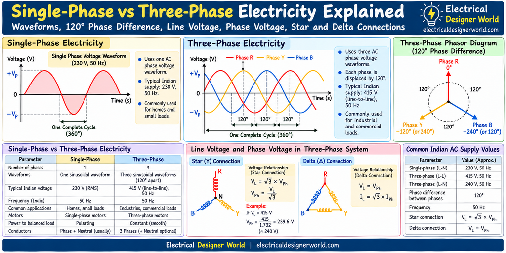
Table of Contents
Electricity is supplied to homes, commercial buildings, factories, and industrial facilities using different electrical distribution systems. Two of the most common systems are single-phase and three-phase electricity.
Understanding single-phase vs three-phase electricity helps electrical engineering students and professionals understand how voltage is supplied to electrical equipment, how motors operate, and why industrial facilities commonly use three-phase power.
In this lesson of our 30 Day Electrical Fundamentals course, we will explore single-phase supply, three-phase supply, phase difference, line voltage, phase voltage, neutral, and star and delta connections.
By the end of this lesson, you will understand the basic differences between these systems and how to calculate voltage relationships in a balanced three-phase system.
What Is Single-Phase Electricity?
Single-phase electricity is an AC electrical supply that uses one alternating voltage waveform.
The voltage rises and falls periodically, changing polarity during each cycle. In a typical single-phase system, the supply has a phase conductor and may have a neutral conductor.
In India, a typical household supply is approximately 230 V AC at 50 Hz.
This means the voltage has a nominal RMS value of 230 V and completes 50 cycles per second.
How Does Single-Phase Electricity Work?
A single-phase AC source produces a voltage that varies sinusoidally with time.
The instantaneous voltage can be represented by:
v(t) = Vm sin(ωt)
Where:
- v(t) = Instantaneous voltage
- Vm = Peak voltage
- ω = Angular frequency in radians per second
- t = Time in seconds
The waveform alternates between positive and negative values.
Single-phase electricity is commonly used for lighting, fans, televisions, computers, and many household appliances.
Advantages of Single-Phase Electricity
- Simple supply arrangements for many small loads.
- Commonly used in residential buildings.
- Suitable for many low-power appliances.
- Often economical for small electrical installations.
However, single-phase motors generally have limitations compared with three-phase motors of similar ratings, particularly regarding starting arrangements and smooth torque production.
What Is Three-Phase Electricity?
Three-phase electricity is an AC system consisting of three alternating voltages of the same frequency, usually with equal magnitudes in a balanced system.
The three phase voltages are displaced from each other by 120 electrical degrees.
The phases are commonly labelled R, Y, and B in India, or L1, L2, and L3 in many modern drawings and standards.
How Does Three-Phase Electricity Work?
In a balanced three-phase system, the three sinusoidal phase voltages can be represented as:
vR = Vm sin(ωt)
vY = Vm sin(ωt − 120°)
vB = Vm sin(ωt − 240°)
Each phase has the same frequency and peak magnitude, but the waveforms reach corresponding points at different times.
The 120° displacement allows three-phase systems to deliver power effectively to balanced loads.
In an ideal balanced three-phase system supplying a balanced load, the total instantaneous power is constant. This is particularly useful for industrial motors and other three-phase equipment.
Advantages of Three-Phase Electricity
- Suitable for many industrial and commercial loads.
- Supports efficient power transmission and distribution.
- Provides smooth torque in balanced three-phase motors.
- Can supply both three-phase equipment and single-phase loads in suitable four-wire systems.
- Is widely used for pumps, compressors, large HVAC systems, and industrial machinery.
Three-phase systems require appropriate protection, switching equipment, conductor sizing, and earthing arrangements.
Single-Phase vs Three-Phase Electricity: Key Differences
The following table summarises the main differences between single-phase and three-phase electricity.
| Parameter | Single-phase | Three-phase |
|---|---|---|
| AC waveforms | One phase voltage waveform | Three phase voltage waveforms |
| Phase displacement | Not applicable between multiple phases | 120° between phases |
| Typical Indian supply voltage | Approximately 230 V | Commonly 415 V between lines |
| Frequency in India | 50 Hz | 50 Hz |
| Common applications | Homes and small loads | Industrial and commercial loads |
| Motors | Single-phase motors | Three-phase motors |
| Power delivery to balanced loads | Pulsates over the cycle for a resistive load | Total instantaneous power is constant for a balanced load |
| Conductors | Often phase and neutral | Three phases, with or without neutral depending on the system |
Actual supply voltages and arrangements depend on the distribution network and installation.
Why Are Three Phases Separated by 120 Degrees?
One complete AC cycle represents 360 electrical degrees.
In a balanced three-phase system, the three phases are equally spaced around this cycle.
Therefore:
360° ÷ 3 = 120°
The phase displacement is 120 electrical degrees.
This means that when one phase reaches its positive peak, the other two phases are at different points in their cycles.
This balanced arrangement is fundamental to the operation of three-phase electrical machines and power systems.
Example of Three-Phase Phase Displacement
Imagine three voltage waveforms with identical amplitudes and frequencies.
- Phase R begins at 0°.
- Phase Y is displaced by 120°.
- Phase B is displaced by 240° relative to Phase R.
The waveforms are evenly distributed across one complete cycle.
Diagram suggestion: Add three sinusoidal waveforms labelled R, Y, and B, with 120° phase displacement markers.
Image ALT text: Single-Phase vs Three-Phase Electricity showing three-phase voltage waveforms separated by 120 degrees.
What Is Line Voltage in a Three-Phase System?
Line voltage is the voltage measured between any two phase conductors.
For example:
- R–Y voltage
- Y–B voltage
- B–R voltage
In a typical Indian low-voltage three-phase distribution system, the nominal line-to-line voltage is approximately 415 V.
Line voltage is important when selecting equipment such as three-phase motors, switchgear, transformers, and distribution panels.
What Is Phase Voltage in a Three-Phase System?
Phase voltage is the voltage across an individual phase of a source or load, depending on the connection and measurement reference.
In a star-connected system, phase voltage is measured between a phase and the star point. When the star point is connected to neutral, this is the phase-to-neutral voltage.
For a balanced star-connected system:
VLine = √3 × VPhase
Therefore:
VPhase = VLine / √3
Line Voltage and Phase Voltage Calculation
Suppose a balanced star-connected system has a line voltage of 415 V.
Given:
VLine = 415 V
Formula:
VPhase = VLine / √3
Calculation:
VPhase = 415 / 1.732
VPhase ≈ 239.6 V
Therefore, the phase voltage is approximately 240 V.
This is why a nominal 415 V line-to-line system has a phase-to-neutral voltage close to 230–240 V, depending on the specified nominal system voltage.
Important: The √3 relationship applies to a balanced star-connected system. In a delta connection, the line voltage equals the phase voltage.
What Is a Star Connection in a Three-Phase System?
A star connection is also called a Y connection.
In a star-connected system, one end of each of the three phase windings or load impedances is connected to a common point called the star point.
The other three ends connect to the three line conductors.
The star point may be connected to neutral, depending on the system design.
Star Connection Voltage Relationship
For a balanced star-connected system:
VLine = √3 × VPhase
ILine = IPhase
Where:
- VLine = Line-to-line voltage
- VPhase = Phase voltage
- ILine = Line current
- IPhase = Phase current
Star connections are commonly used in distribution systems and in various motor and transformer arrangements.
What Is a Delta Connection in a Three-Phase System?
A delta connection is also called a Δ connection.
In a delta-connected system, the three phase windings or load impedances are connected end-to-end to form a closed loop.
The three line conductors connect to the three junctions of the loop.
Delta Connection Voltage Relationship
For a balanced delta-connected system:
VLine = VPhase
ILine = √3 × IPhase
Where:
- VLine = Line-to-line voltage
- VPhase = Voltage across each delta phase
- ILine = Line current
- IPhase = Current through each delta phase
Delta connections are used in many three-phase motor and transformer applications.
The actual connection depends on equipment ratings, the supply voltage, and the manufacturer’s instructions.
What Is the Role of Neutral in a Three-Phase System?
Neutral is a conductor connected to the neutral point of a suitable electrical system, commonly the star point of a star-connected source or transformer.
In a three-phase, four-wire distribution system, neutral can provide a return path for single-phase loads connected between a phase and neutral.
For a balanced three-phase load, the phase currents sum to zero at every instant, so the ideal neutral current is zero.
For an unbalanced load, neutral current may flow. Harmonics and other non-ideal conditions can also affect neutral current.
Neutral is not a substitute for a protective earth conductor. They have different functions and must be treated according to the applicable electrical standards.
Practical Example: Understanding a 415 V Three-Phase Supply
Suppose an industrial facility uses a balanced three-phase, four-wire supply with a nominal line voltage of 415 V.
Calculate the phase voltage for a balanced star-connected system.
Given:
Line voltage = 415 V
Formula:
VPhase = VLine / √3
Calculation:
VPhase = 415 / 1.732
VPhase ≈ 239.6 V
Therefore:
- Line-to-line voltage ≈ 415 V
- Line-to-neutral voltage ≈ 240 V
In practice, the actual nominal supply specification may be stated as 400/230 V or 415/240 V, depending on the system and applicable requirements. Always use the specified voltage for the project.
Where Are Single-Phase and Three-Phase Systems Used?
Single-phase electricity is commonly used for:
- Residential lighting and fans.
- Computers and small office equipment.
- Household appliances.
- Small electrical loads.
Three-phase electricity is commonly used for:
- Industrial motors and pumps.
- Compressors and process equipment.
- Large HVAC systems.
- Industrial distribution panels.
- Manufacturing machinery.
- Commercial and industrial power distribution.
In EPC projects, electrical designers must understand the supply arrangement when selecting equipment, preparing single-line diagrams, and coordinating power distribution.
Frequently Asked Questions About Single-Phase vs Three-Phase Electricity
1. What is the main difference between single-phase and three-phase electricity?
Single-phase electricity uses one AC phase voltage waveform. Three-phase electricity uses three phase voltage waveforms separated by 120 electrical degrees.
2. Why is three-phase electricity used in industries?
Three-phase systems are suitable for industrial loads because they support efficient power distribution and smooth torque production in balanced three-phase motors.
3. Is 415 V the phase voltage or line voltage?
In a typical 415 V three-phase star-connected distribution system, 415 V is the line-to-line voltage. The phase-to-neutral voltage is approximately 240 V.
4. What is the difference between star and delta connections?
A star connection joins one end of each phase to a common point. A delta connection joins the three phases end-to-end to form a closed loop. Their line and phase voltage and current relationships differ.
5. Does a three-phase system always require a neutral?
No. Many three-phase loads, such as balanced three-phase motors, operate using three phase conductors without a neutral. A neutral is needed where the system design requires it, including many four-wire distribution systems supplying single-phase loads.
Practice Questions: Single-Phase vs Three-Phase Electricity
Question 1: What is the phase displacement between the voltages in a balanced three-phase system?
A. 60°
B. 90°
C. 120°
D. 180°
Question 2: What is the approximate phase voltage of a 415 V line-voltage star-connected system?
A. 120 V
B. 230 V
C. 415 V
D. 720 V
Question 3: In a balanced star connection, what is the relationship between line current and phase current?
A. ILine = √3 × IPhase
B. ILine = IPhase
C. IPhase = √3 × ILine
D. ILine = 3 × IPhase
Question 4: In a balanced delta connection, what is the relationship between line voltage and phase voltage?
A. VLine = √3 × VPhase
B. VLine = VPhase
C. VPhase = 3 × VLine
D. VLine = 0.5 × VPhase
Question 5: Which supply is commonly used for many industrial three-phase motors?
A. Single-phase supply only
B. Three-phase supply
C. DC supply only
D. No electrical supply
Answers
- C — 120°.
- B — Approximately 240 V, closest to 230 V.
- B — Line current equals phase current in a star connection.
- B — Line voltage equals phase voltage in a delta connection.
- B — Three-phase supply.
Conclusion
Single-phase and three-phase electricity are fundamental parts of electrical power systems.
Single-phase supply is commonly used for residential and smaller electrical loads, while three-phase supply is widely used for industrial equipment and power distribution.
Understanding 120° phase displacement, line voltage, phase voltage, neutral, and star and delta connections will help you build a strong foundation for studying three-phase power, electrical machines, and industrial distribution systems.
Continue practising the voltage relationships and reviewing the waveform diagrams before moving to the next lesson.
Continue the 30 Day Electrical Fundamentals Course
This lesson is part of the Electrical Fundamentals – Zero to Advanced course on Electrical Designer World.
- Previous lesson: Day 12 – RMS and Peak Values
- Current lesson: Day 13 – Single-Phase vs Three-Phase Electricity
- Next lesson: Day 14 – Three-Phase Power: kW, kVA, kVAR and Power Factor
Further reading: All About Circuits – Textbook for additional learning resources on AC circuits and three-phase electrical principles.