
How to Read an Electrical SLD in EPC Projects
Introduction
Learning how to read electrical SLD drawings is an essential skill for electrical engineers and designers working on EPC projects. An electrical single line diagram (SLD) shows how power flows from the incoming supply through transformers, switchgear, feeders and protective devices to electrical loads.
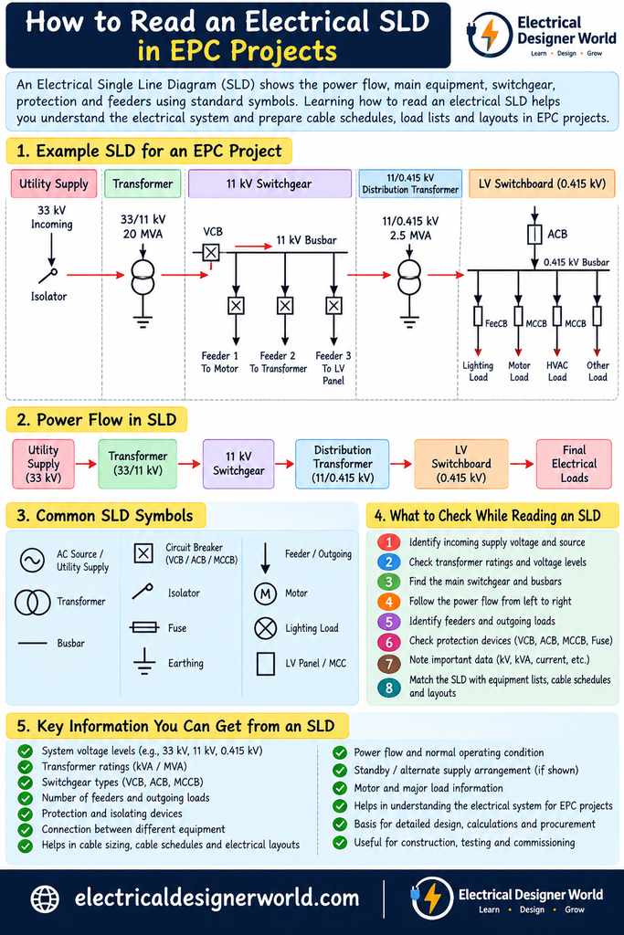
Table of Contents
A Single Line Diagram (SLD) is one of the most important documents in an EPC electrical project.
You already learned the basics of an SLD in an earlier lesson. Now we will go one level deeper and learn how to read a practical industrial SLD.
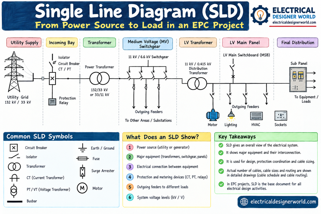
The goal is simple:
When you open a real EPC electrical SLD, you should be able to follow the power from the source all the way to the load.
For example:
Power enters → Transformer reduces voltage → Breaker protects the circuit → Busbar distributes power → Feeder goes to MCC → Cable feeds the motor.
Once you develop this way of thinking, even a complicated SLD becomes much easier to understand.
1. What Is an SLD?
SLD stands for Single Line Diagram.
An SLD is a simplified drawing used to represent an electrical system.
Instead of drawing all three phases separately:
R ─────────────
Y ─────────────
B ─────────────
a three-phase circuit can be represented using a single line:
──────────────This makes large electrical systems easier to read and understand.
2. Why Is the SLD Important in EPC?
Think of the SLD as the electrical map of the plant.
It shows important information such as:
- Electrical power sources
- Voltage levels
- Transformers
- Switchboards
- Circuit breakers
- Busbars
- Feeders
- Motors
- Generators
- UPS systems
- Protection
- Metering
- Power distribution arrangement
The SLD can be considered the skeleton of the electrical system because many other engineering activities are connected to it.
3. Start With the Power Source
Consider a simple industrial plant where the utility supplies 11 kV.
A simplified system could look like this:
             UTILITY
                │
              11 kV
                │
                ▼
           INCOMING CB
                │
                ▼
           11 kV BUSBAR
                │
                ▼
           TRANSFORMER
         11 kV / 415 V
                │
                ▼
            LV MAIN CB
                │
                ▼
             LV BUSBAR
When you first open an SLD, identify the source of electrical power.
Then follow where that power goes.
4. Trace the Power Flow
Don’t try to understand every symbol at the same time.
Instead, follow the power flow.
For example:
UTILITY
   ↓
INCOMER
   ↓
MV BUS
   ↓
TRANSFORMER
   ↓
LV INCOMER
   ↓
LV BUS
   ↓
FEEDER
   ↓
MCC
   ↓
MOTOR
When reading an SLD, continuously ask:
Where does the power come from?
Then:
Where does it go next?
And:
What protects it?
This simple approach makes SLD reading much easier.
5. What Is an Incomer?
An incomer is the circuit that brings electrical power into a switchboard or busbar.
For example:
Transformer
     │
     ▼
    ACB
     │
     ▼
 LV BUSBAR
Here, the ACB forms part of the incoming circuit.
In simple terms:
Incomer = the incoming power path to a board.
6. What Is an Outgoing Feeder?
An outgoing feeder carries power from a switchboard to another piece of equipment or another distribution board.
For example:
LV BUSBAR
    │
    ├──── Feeder → MCC
    │
    ├──── Feeder → DB
    │
    └──── Feeder → Transformer
The busbar receives power through the incomer and distributes it through outgoing feeders.
Therefore:
INCOMER
   ↓
BUSBAR
   ↓
OUTGOING FEEDERS
This is one of the most important concepts when reading an SLD.
7. What Is a Busbar?
A busbar is a common conductor used to distribute electrical power inside a switchboard.
A useful way to visualize it is as an electrical highway:
             BUSBAR
════════════════════════════
      │       │       │
      │       │       │
      ▼       ▼       ▼
    MCC-1    DB-1    MCC-2
Power enters the busbar and is distributed to multiple outgoing feeders.
Busbars have ratings such as:
- Continuous current rating
- Short-circuit withstand rating
- Voltage rating
8. Main Incomer
Suppose a transformer is rated:
1000 kVA, 11 kV / 415 V
The transformer secondary feeds an LV switchboard:
1000 kVA Transformer
        │
        ▼
      ACB
        │
        ▼
    LV BUSBAR
The ACB is the main incomer of the LV switchboard.
For a three-phase transformer, the approximate LV full-load current can be calculated using:
I = S / (√3 × V)
Where:
- S = Transformer apparent power in VA
- V = Line voltage
For:
- S = 1000 kVA
- V = 415 V
the current is approximately:
1,391 A
Therefore, the LV incomer needs to be engineered around the operating current, along with fault level, design margin and project requirements.
9. What Is a Bus Coupler?
An electrical switchboard may have two bus sections.
       BUS SECTION A
═══════════════════════
          │
       BUS COUPLER
          │
═══════════════════════
       BUS SECTION B
The device connecting the two sections is called a:
Bus Coupler
Depending on the operating philosophy, a bus coupler may provide:
- Bus-section interconnection
- Supply transfer
- Maintenance flexibility
- Redundancy
- Isolation of a faulty section
The exact arrangement depends on the project requirements.
10. Why Split a Busbar?
Instead of having one large busbar:
══════════════════════════════
     │    │    │    │    │
a switchboard can have separate bus sections:
═══════════════╤═══════════════
               │
           BUS COUPLER
Bus segmentation can provide greater operating and maintenance flexibility.
The exact protection and switching philosophy must be defined for the particular project.
11. Transformer on an SLD
A transformer is represented on an SLD using a transformer symbol.
Conceptually:
11 kV BUS
   │
   │
 ╔══════╗
 ║  TX  ║
 ╚══════╝
   │
   ▼
415 V BUS
The transformer performs voltage conversion:
11 kV
  ↓
Transformer
  ↓
415 V
When reading a transformer on an SLD, check:
Primary Voltage
What voltage enters the transformer?
Secondary Voltage
What voltage leaves the transformer?
Rating
What is its kVA or MVA rating?
Impedance
What is the transformer impedance?
Vector Group
What transformer connection/vector group is specified?
These parameters can affect the downstream electrical system.
12. MV and LV Sections
An industrial plant can contain multiple voltage levels.
For example:
UTILITY
  │
132 kV
  │
  ▼
MAIN TRANSFORMER
  │
  ▼
33 kV
  │
  ▼
33 kV SWITCHGEAR
  │
  ▼
11 kV TRANSFORMER
  │
  ▼
11 kV SWITCHGEAR
  │
  ▼
11/0.415 kV TRANSFORMER
  │
  ▼
415 V SWITCHBOARD
However, don’t assume that every plant uses these exact voltage levels.
The actual voltage levels are determined by the project’s Electrical Design Basis.
13. MV Switchgear
For an 11 kV system, you may see a:
VCB — Vacuum Circuit Breaker
A simplified arrangement is:
11 kV BUSBAR
════════════════════
     │
     │
    VCB
     │
     ▼
Transformer
MV switchgear may also include:
- CTs
- VTs
- Protection relays
- Isolators
- Earthing switches
- Metering
14. What Is a CT?
CT = Current Transformer
A CT is used to sense electrical current and provide a scaled current signal for protection and measurement.
Conceptually:
Power Circuit
     │
    CT
     │
     ▼
Protection Relay
The protection and measurement system does not directly handle the full power-system current.
The CT provides the required measurement signal.
15. What Is a VT/PT?
VT = Voltage Transformer
You may also see:
PT = Potential Transformer
A VT/PT provides a scaled voltage signal for:
- Measurement
- Protection
- Monitoring
Conceptually:
11 kV BUS
    │
   VT
    │
    ▼
Meter / Relay
An easy way to remember:
CT → Current
VT → Voltage
16. Protection Relay
The protection relay acts as a decision-maker within a protection scheme.
A simplified sequence is:
Fault
  ↓
CT / VT
  ↓
Protection Relay
  ↓
Trip Command
  ↓
Circuit Breaker
  ↓
Circuit Opens
The relay detects abnormal electrical conditions based on its protection functions and sends a trip command when required.
17. Circuit Breaker
The circuit breaker is the device that actually opens the power circuit when commanded by protection or control systems.
The basic sequence is:
Fault
 ↓
CT / VT
 ↓
Relay
 ↓
Trip
 ↓
Breaker Opens
 ↓
Fault Isolated
A simple way to remember:
Relay detects and decides.
Breaker interrupts the circuit.
18. Outgoing Feeder to an MCC
Let’s follow one outgoing feeder:
LV BUSBAR
    │
    ▼
   MCCB
    │
    ▼
  CABLE
    │
    ▼
   MCC
The MCC can then supply multiple motors:
                 MCC
       ┌─────────┼─────────┐
       │         │         │
       ▼         ▼         ▼
    Motor 1   Motor 2   Motor 3
This is how the SLD connects the main distribution system to motor loads.
19. PCC vs MCC
Two terms you will frequently encounter in EPC projects are:
PCC — Power Control Center
A PCC is primarily associated with power distribution.
Transformer
    ↓
   PCC
    ↓
Various feeders
MCC — Motor Control Center
An MCC is primarily associated with motor feeders and motor control.
PCC
 ↓
MCC
 ↓
Motors
This distinction is useful when reading industrial SLDs.
20. Generator Connection
Industrial plants may also have an emergency or standby generator.
A simplified arrangement is:
             UTILITY
                │
                ▼
           MAIN SWITCHBOARD
                │
                ├────────── Loads
                │
                │
             ATS / ACB
                │
                ▼
            GENERATOR
The actual arrangement varies depending on the project’s emergency-power philosophy.
The important concept is:
Generator = alternate electrical source.
21. UPS on an SLD
A UPS provides backup power to critical loads.
A simplified arrangement is:
Normal AC
   │
   ▼
 UPS
   │
   ▼
Critical Load
   ▲
   │
 Battery
Critical loads can include selected:
- Control systems
- Instrumentation
- Emergency systems
- Communication equipment
- Critical PLC/control equipment
The actual critical-load list depends on the project.
22. Motor Feeder on an SLD
Let’s look at one motor feeder:
LV BUSBAR
    │
    ▼
   MCCB
    │
    ▼
STARTER / VFD
    │
    ▼
   CABLE
    │
    ▼
   MOTOR
This connects the distribution system to the motor.
The SLD gives you the big picture, while detailed motor-feeder engineering provides the individual design calculations and equipment details.
23. How to Read an SLD Like an EPC Engineer
When you receive an SLD, use this sequence.
Question 1 — Where is the power coming from?
- Utility?
- Generator?
- Another switchboard?
Question 2 — What is the voltage?
- 11 kV?
- 415 V?
- 33 kV?
Question 3 — What equipment changes the voltage?
Usually, a transformer.
Question 4 — What protects the circuit?
- ACB?
- VCB?
- MCCB?
- Fuse?
Question 5 — Where is the busbar?
Which loads are connected to it?
Question 6 — Where do the outgoing feeders go?
- MCC?
- DB?
- Transformer?
- Motor?
Question 7 — What is the protection scheme?
- CT?
- VT?
- Relay?
- Breaker?
Question 8 — Is there redundancy?
Look for:
- Bus coupler
- Standby transformer
- Generator
- Dual supply
This approach makes a complicated SLD much easier to understand.
24. Complete Simple Industrial SLD Example
Let’s put everything together:
                    UTILITY
                       │
                     11 kV
                       │
                      VCB
                       │
                 11 kV BUSBAR
                       │
                       ▼
                11/0.415 kV
                 TRANSFORMER
                       │
                       ▼
                      ACB
                       │
                 415 V BUSBAR
             ═══════════════════
               │       │       │
               │       │       │
               ▼       ▼       ▼
              MCC     DB     UPS
               │
          Motor Feeders
          ┌────┼────┐
          │    │    │
          ▼    ▼    ▼
        M-01 M-02 M-03
Now trace the power:
Utility
 ↓
11 kV
 ↓
VCB
 ↓
11 kV Bus
 ↓
Transformer
 ↓
415 V
 ↓
ACB
 ↓
415 V Bus
 ↓
MCC
 ↓
Motor Feeder
 ↓
Motor
This is the basic skill of SLD reading.
Understand Electrical Power Flow in an EPC Project
To understand how electrical power flows from the incoming supply to the final electrical loads, you must first learn the basics of voltage, current, and power. Read our guide on What Is Potential Difference in Simple Terms? to understand how voltage drives current through an electrical circuit.
25. What Information Can You Extract From an SLD?
A good EPC engineer can obtain a significant amount of system-level information from an SLD.
Electrical Sources
- Utility
- Generator
- UPS
- Emergency source
Voltage Levels
- HV
- MV
- LV
Major Equipment
- Transformers
- Switchboards
- MCCs
- PCCs
- DBs
Protection
- Circuit breakers
- CTs
- VTs
- Relays
Distribution
- Busbars
- Incomers
- Outgoing feeders
- Bus couplers
Loads
- Motors
- Lighting
- Utility loads
- Critical loads
26. SLD and Other Engineering Documents
The SLD does not exist in isolation.
It connects with many other engineering documents.
             DESIGN BASIS
                  │
                  ▼
              LOAD LIST
                  │
                  ▼
                 SLD
             ┌────┼────┐
             │    │    │
             ▼    ▼    ▼
        Load Flow  Short Circuit
             │    │
             ▼    ▼
        Protection Study
             │
             ▼
       Cable Schedule
             │
             ▼
        Equipment Specs
This is one reason the SLD is so important.
Changes to the SLD can affect many other engineering documents.
27. SLD and Load List
The load list tells you:
What loads exist?
The SLD tells you:
How are those loads supplied?
For example:
Load List
| Equipment | Load |
|---|---|
| Motor-01 | 75 kW |
| Motor-02 | 110 kW |
| Motor-03 | 45 kW |
The SLD may show:
MCC
 │
 ├── Motor-01
 ├── Motor-02
 └── Motor-03
The two documents need to remain consistent.
28. SLD and Cable Schedule
The SLD may tell you:
MCC
 ↓
Motor-01
The cable schedule contains the detailed cable information, such as:
- Cable tag
- Cable size
- Cable type
- Number of runs
- Length
- From
- To
- Installation method
Therefore:
SLD = system-level picture
Cable Schedule = detailed cable information
29. SLD and Short-Circuit Study
Suppose the SLD shows:
Transformer
    ↓
415 V Bus
    ↓
MCC
A short-circuit study determines the fault level at different points in the system.
Conceptually:
Transformer
     ↓
415 V Bus
     ↓
Fault Level
     ↓
Breaker Rating
This helps determine whether the switchgear has sufficient short-circuit capability.
30. The SLD Is a Living Engineering Document
During an EPC project, the SLD can change.
For example:
Initial Design
     ↓
Client Comments
     ↓
Engineering Changes
     ↓
Vendor Information
     ↓
Updated SLD
     ↓
Construction
     ↓
As-Built SLD
Therefore, revision control is extremely important.
You may see revisions such as:
- Rev 0
- Rev 1
- Rev 2
- IFC
- As-Built
depending on the project’s document-control system.
🧠 The Most Important SLD Skill
Don’t try to memorize every electrical symbol.
Instead, develop this habit:
TRACE THE POWER.
Whenever you see an SLD, ask:
WHERE DOES POWER COME FROM?
             ↓
WHAT VOLTAGE?
             ↓
WHAT BREAKER?
             ↓
WHAT TRANSFORMER?
             ↓
WHAT BUSBAR?
             ↓
WHAT FEEDER?
             ↓
WHERE DOES IT GO?
             ↓
WHAT LOAD?
If you can answer those questions, you can already understand a large part of an industrial SLD.
🎯 EPC Engineer Exercise
Consider this simplified system:
       UTILITY
          │
        11 kV
          │
         VCB
          │
      11 kV BUS
          │
     TRANSFORMER
    11/0.415 kV
          │
         ACB
          │
      415 V BUS
       │       │
       │       │
      MCC      DB
       │
      MCCB
       │
      CABLE
       │
     75 kW
     MOTOR
Try answering these questions:
- What is the incoming voltage?
- Which breaker is used on the 11 kV side?
- What is the transformer voltage ratio?
- Which breaker is shown on the LV transformer incomer?
- What is the purpose of the 415 V busbar?
- What does the MCC supply?
- What device protects the motor feeder in this simplified example?
- What carries power from the MCCB to the motor?
- Trace the complete power path from utility to motor.
- What information would you need before designing the complete feeder for the 75 kW motor?
🔑 Key Takeaways
After this lesson, you should understand:
- An SLD is the electrical map of a plant.
- An incomer brings power into a board.
- An outgoing feeder carries power from the board to a load or another board.
- A busbar distributes power to multiple feeders.
- A transformer changes voltage levels.
- A CT provides current measurement signals.
- A VT/PT provides voltage measurement signals.
- A relay detects abnormal conditions and issues trip commands when required.
- A circuit breaker interrupts the circuit.
- An MCC is mainly associated with motor feeders and control.
- An SLD should always be read by tracing the power flow.
Conclusion
An SLD may initially look like a complicated collection of symbols, lines and abbreviations.
But you don’t need to memorize everything.
Start with one question:
“Where does the power come from, and where does it go?”
Then trace:
Source → Breaker → Busbar → Transformer → Breaker → Busbar → Feeder → MCC → Motor
Once you develop this habit, you can start reading real industrial SLDs with much more confidence.
And that is one of the most important skills for an Electrical EPC Engineer.