
Magnetism in Electrical Engineering: A Beginner’s Guide
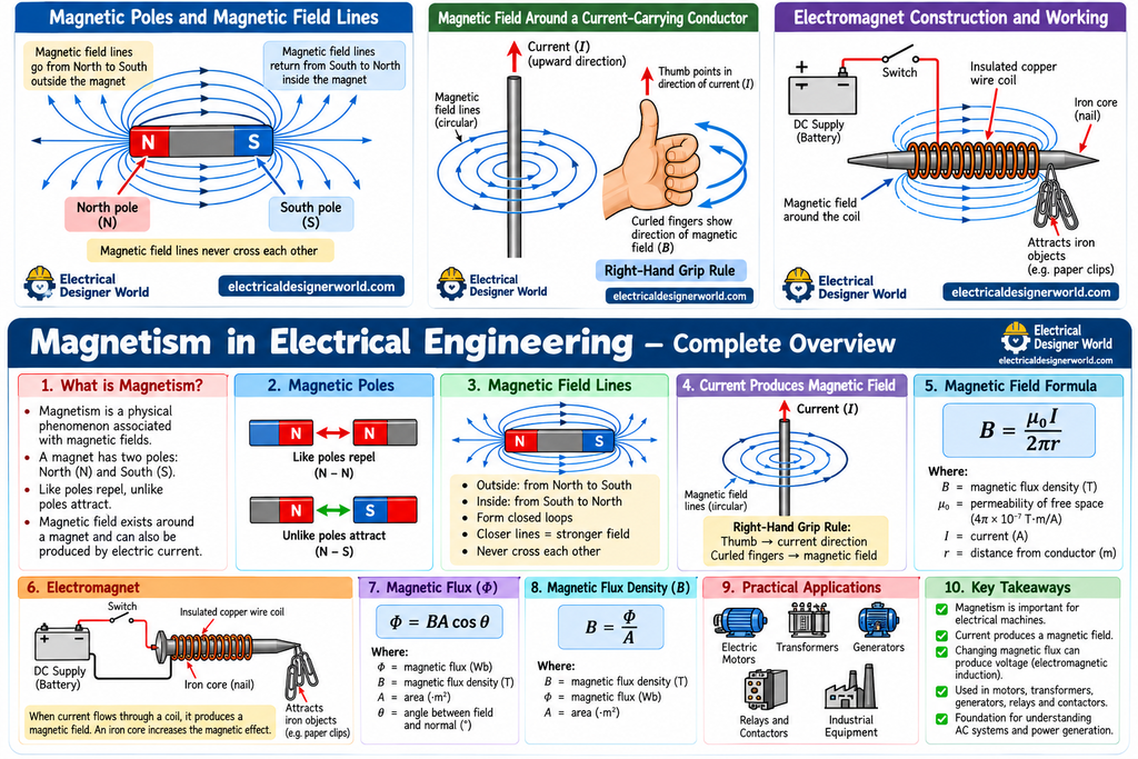
Magnetism in electrical engineering is an important concept that explains how electric motors rotate, how transformers transfer electrical energy, and how generators produce electricity. In this beginner-friendly guide, you will learn about magnetic poles, magnetic fields, electromagnets, magnetic flux, formulas, and practical applications with simple examples.
Table of Contents
Welcome to Day 8 of the Electrical Fundamentals: Zero to Advanced series on Electrical Designer World. This lesson starts with the basics and gradually connects magnetism to real electrical equipment used in homes, buildings, and industrial plants.
1. What Is Magnetism?
Magnetism is a physical phenomenon associated with magnetic fields. It can cause magnets and certain materials to attract or repel one another.
For example, when you bring a magnet near an iron nail, the nail may be attracted to the magnet. This happens because of the magnetic interaction between them.
A magnet has two poles:
- North pole (N): One end of a magnet.
- South pole (S): The opposite end of a magnet.
The basic rules of magnetism are:
- Like poles repel each other.
- Unlike poles attract each other.
- A magnetic field exists around a magnet.
- Electric current can also produce a magnetic field.
These principles form the foundation of magnetism in electrical engineering.
2. What Is a Magnetic Field?
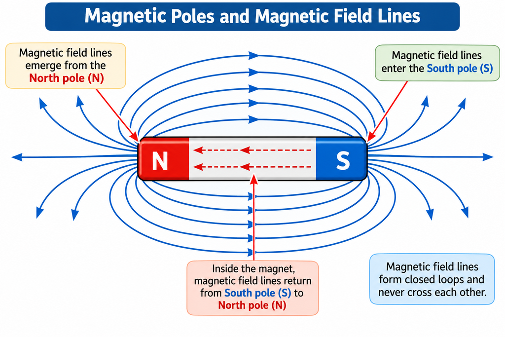
A magnetic field is the region around a magnet or a current-carrying conductor where magnetic forces can be observed.
Magnetic fields are represented using magnetic field lines. These lines help us understand the direction and relative strength of a magnetic field.
For a bar magnet:
- Outside the magnet, field lines are represented as travelling from North to South.
- Inside the magnet, the lines return from South to North, forming closed loops.
- Closely spaced field lines represent a stronger magnetic field in the illustration.
- Magnetic field lines do not cross one another.
Remember that magnetic field lines are a visual representation of a magnetic field. They are not physical wires.
For additional information, read OpenStax: Magnetic Fields, Field Lines, and Force.
3. What Happens When Electric Current Flows Through a Wire?
One of the most important principles in electrical engineering is that an electric current produces a magnetic field around a conductor.
When current flows through a straight wire, the magnetic field forms circular patterns around the wire.
The direction of the magnetic field depends on the direction of conventional current.
The right-hand grip rule
The right-hand grip rule helps us determine the direction of the magnetic field around a straight current-carrying conductor.
Follow these steps:
- Imagine holding the conductor with your right hand.
- Point your thumb in the direction of conventional current.
- Your curled fingers indicate the direction of the magnetic field.
This rule is useful when studying electrical conductors, coils, motors, and electromagnetic equipment.
Magnetic field formula for a straight conductor
For a long, straight conductor in free space, the magnetic flux density is approximately:
B = μ₀I / (2πr)
Where:
- B = magnetic flux density in tesla (T)
- μ₀ = permeability of free space
- I = current in amperes (A)
- r = perpendicular distance from the conductor in metres (m)
This formula shows that the magnetic field becomes stronger when current increases and weaker when the observation point moves farther from the wire.
For now, remember the main principle: electric current produces a magnetic field.
Learn more from OpenStax: Magnetic Fields Produced by Currents.
4. What Is an Electromagnet?
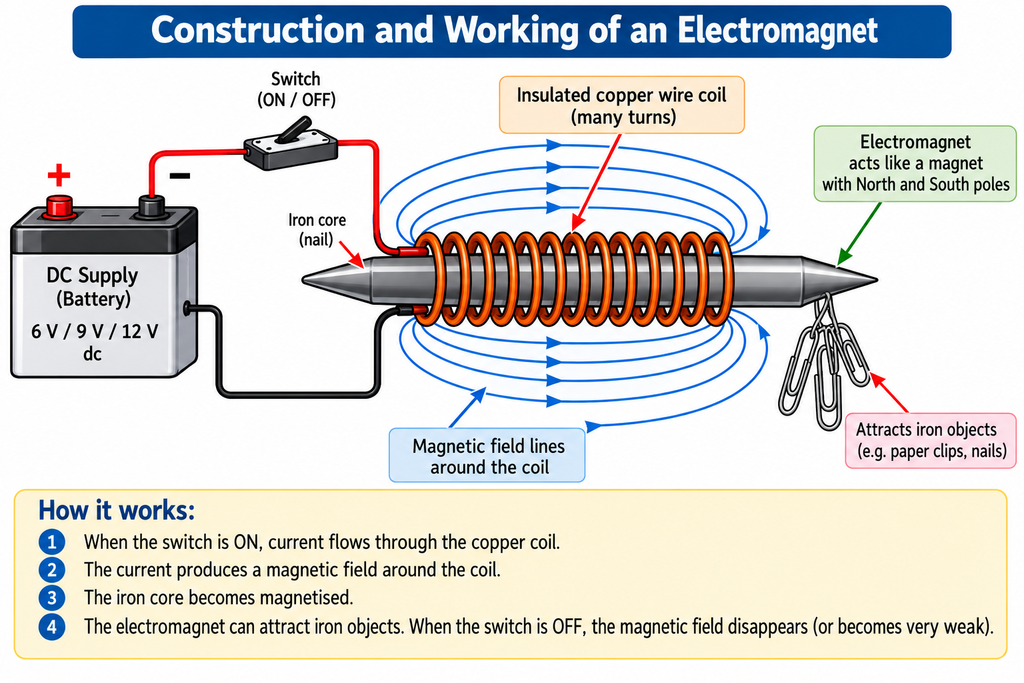
An electromagnet is a magnet produced using electric current.
When current flows through a coil of insulated wire, it creates a magnetic field. Placing a suitable iron core inside the coil can make the magnetic effect much stronger.
How does an electromagnet work?
- Insulated copper wire is wound around an iron core.
- The coil is connected to a suitable electrical supply.
- Electric current flows through the coil.
- A magnetic field is produced.
- The iron core becomes magnetised.
When the current is switched off, the magnetic field produced by the coil largely disappears. However, some core materials may retain residual magnetism.
Applications of electromagnets
Electromagnets are used in:
- Electrical relays
- Contactors
- Solenoid valves
- Electric motors
- Magnetic lifting equipment
For example, a contactor uses an electromagnetic coil to operate its contacts. When the coil is energised, the magnetic force moves the mechanism.
5. What Is Magnetic Flux?
Magnetic flux represents the total magnetic field passing through a specified surface.
It is represented by the Greek letter phi (Φ), and its SI unit is the weber (Wb).
Imagine a flat coil placed inside a magnetic field. The amount of magnetic flux passing through the coil depends on the magnetic field strength, the surface area, and the angle between the field and the surface.
For a uniform magnetic field passing through a flat surface:
Φ = BA cos θ
Where:
- Φ = magnetic flux in webers (Wb)
- B = magnetic flux density in tesla (T)
- A = surface area in square metres (m²)
- θ = angle between the magnetic field and the normal to the surface
When the magnetic field is perpendicular to the surface, θ = 0°. Since cos 0° = 1:
Φ = BA
Worked example: Calculate magnetic flux
Question: A uniform magnetic field of 0.5 T passes perpendicularly through a surface with an area of 0.2 m². Calculate the magnetic flux.
Step 1: Write the formula.
Φ = BA
Step 2: Substitute the values.
Φ = 0.5 × 0.2
Step 3: Calculate the answer.
Φ = 0.1 Wb
Answer: The magnetic flux is 0.1 weber.
This example shows how magnetic flux depends on magnetic flux density and the area through which the field passes.
6. What Is Magnetic Flux Density?
Magnetic flux density describes the magnetic flux passing through a unit area perpendicular to the magnetic field.
It is represented by B and measured in tesla (T).
For a uniform magnetic field perpendicular to a surface:
B = Φ / A
Worked example: Calculate magnetic flux density
Question: A magnetic flux of 0.04 Wb passes uniformly and perpendicularly through an area of 0.02 m². Calculate the magnetic flux density.
Step 1: Write the formula.
B = Φ / A
Step 2: Substitute the values.
B = 0.04 / 0.02
Step 3: Calculate the answer.
B = 2 T
Answer: The magnetic flux density is 2 tesla.
Difference between magnetic flux and magnetic flux density
| Quantity | Symbol | SI unit |
|---|---|---|
| Magnetic flux | Φ | Weber (Wb) |
| Magnetic flux density | B | Tesla (T) |
| Magnetic field strength | H | Ampere per metre (A/m) |
Magnetic flux describes the total flux through a surface, while magnetic flux density describes the flux per unit area perpendicular to the field.
In a simple linear magnetic material, B = μH, where μ is the material’s magnetic permeability.
7. Applications of Magnetism in Electrical Engineering
Magnetism is essential for understanding electrical machines and power systems.
Electric motors
Electric motors use magnetic fields to produce torque and rotation. They convert electrical energy into mechanical energy.
Motors are used in pumps, compressors, fans, conveyors, and industrial machinery.
Transformers
Transformers transfer electrical energy between windings through electromagnetic induction.
An alternating current in the primary winding produces changing magnetic flux in the core. This changing flux induces a voltage in the secondary winding.
Transformers are widely used in power generation, transmission, distribution, and industrial electrical installations.
Generators
Generators convert mechanical energy into electrical energy using electromagnetic induction.
When the magnetic flux linking a conductor or coil changes, a voltage can be induced. This principle is used in electrical power generation.
Relays and contactors
Relays and contactors use electromagnetic coils to operate electrical contacts. They are commonly used in control circuits and industrial electrical systems.
For additional background, read the U.S. Department of Energy’s United States Electricity Industry Primer.
8. Why Is Magnetism Important for Electrical Designers?
For an EPC electrical designer, magnetism is more than a theoretical concept. It helps explain how common electrical equipment works.
Understanding magnetism provides a foundation for learning about:
- Transformer operation and selection
- Motors and motor control circuits
- Contactors and electromagnetic relays
- Generators and AC power generation
- Electrical power distribution systems
Explore more electrical engineering topics on Electrical Designer World, including the site’s Electrical Basics category.
As you progress through this course, you will connect these basic concepts to practical electrical engineering calculations and equipment.
9. Practice Questions
Test your understanding of magnetism with these questions.
Question 1: What happens when two North magnetic poles are brought together?
A. They attract each other.
B. They repel each other.
C. There is no magnetic interaction.
Question 2: What happens around a straight conductor when electric current flows?
A. A magnetic field is produced.
B. The magnetic field must always be zero.
C. The conductor automatically becomes a permanent magnet.
Question 3: What is the SI unit of magnetic flux?
A. Tesla
B. Weber
C. Ampere per metre
Question 4: A magnetic field of 0.4 T passes perpendicularly through an area of 0.5 m². Calculate the magnetic flux.
A. 0.2 Wb
B. 0.8 Wb
C. 2 Wb
Answers
- B — Like magnetic poles repel each other.
- A — An electric current produces a magnetic field around the conductor.
- B — Magnetic flux is measured in webers.
- A — Φ = BA = 0.4 × 0.5 = 0.2 Wb.
10. Frequently Asked Questions
What is magnetism in electrical engineering?
Magnetism in electrical engineering is the study of magnetic fields and their effects in electrical equipment such as motors, transformers, generators, relays, and contactors.
Does electric current produce a magnetic field?
Yes. Electric current produces a magnetic field around a conductor. The field’s direction depends on the direction of conventional current.
What is the difference between a permanent magnet and an electromagnet?
A permanent magnet retains its magnetism without a continuously supplied electric current. An electromagnet produces its magnetic field using current through a coil.
What is the difference between magnetic flux and magnetic flux density?
Magnetic flux is the total magnetic flux through a specified surface and is measured in webers. Magnetic flux density is the flux per unit area perpendicular to the field and is measured in tesla.
Can magnetism produce electricity?
Yes. A changing magnetic flux linking a conductor or coil can induce a voltage. This process is called electromagnetic induction and is used in generators and transformers.
Why is magnetism important for electrical engineers?
Magnetism helps electrical engineers understand the operating principles of transformers, motors, generators, relays, and other electromagnetic equipment.
11. Conclusion
Magnetism is one of the fundamental concepts of electrical engineering. In this lesson, we learned about magnetic poles, magnetic fields, current-carrying conductors, electromagnets, magnetic flux, and magnetic flux density.
The most important principle to remember is that electric current can produce a magnetic field, while a changing magnetic flux can induce voltage in a conductor or coil.
These concepts form the foundation for understanding electromagnetic induction, AC generators, transformers, and electric motors.
In the next lesson, we will study Day 9: Electromagnetic Induction — How Changing Magnetic Fields Produce Voltage.
Continue learning with Electrical Designer World and follow the Electrical Fundamentals series step by step.