
⚡ What Is Neutral in Electrical? Complete Beginner’s Guide
If you are starting to learn electrical engineering, one of the first questions you may have is:
What is Neutral in an electrical system?
You will see the word Neutral (N) everywhere:
- Electrical SLDs
- Distribution boards
- Panels
- Cables
- Motors
- Transformers
- Residential wiring
- Industrial electrical systems
But what exactly does neutral do?
Why do we need it?
Does neutral carry current?
What is the difference between Neutral and Earth?
And why is neutral sometimes connected to the transformer?
Let’s understand what is neutral from the basic level, step by step.
1. What Is Neutral?
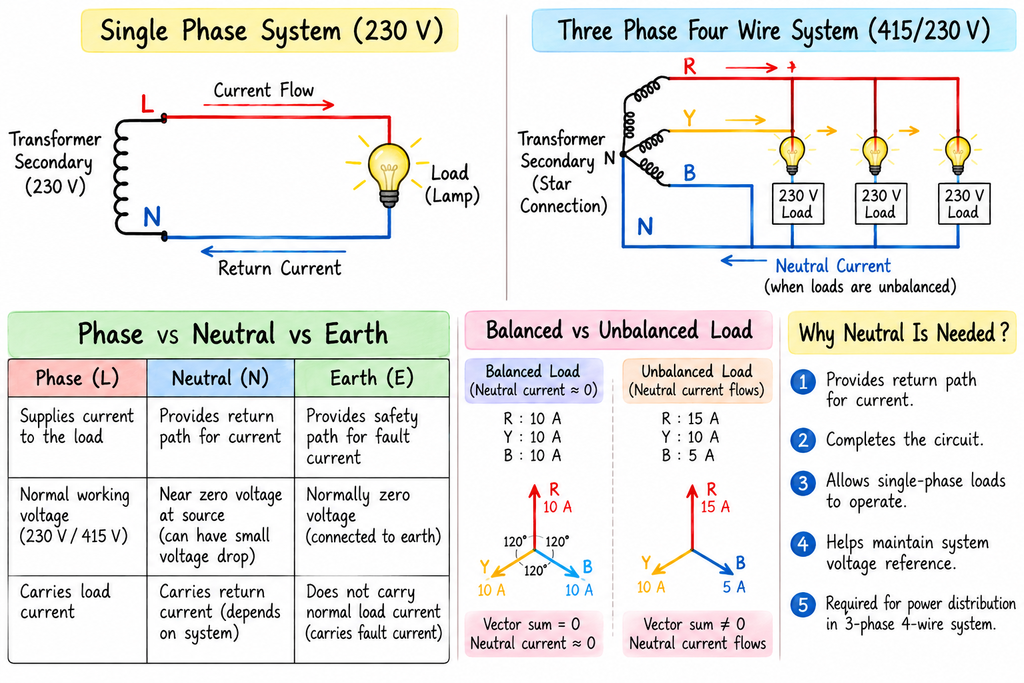
In a simple electrical circuit, neutral is a conductor that provides a return path for current back toward the source.
For a basic single-phase circuit, we can visualize it like this:
       SOURCE
      TRANSFORMER
          │
          │
       PHASE (L)
          │
          ↓
       💡 LOAD
          │
          │
      NEUTRAL (N)
          │
          ↓
       SOURCE
The phase conductor carries current from the source toward the load.
The neutral conductor provides the return path for the circuit current.
So, at a basic level:
Phase supplies the load, and neutral provides the return path.
However, neutral is not simply “a wire that always carries current.” Its current depends on the type and condition of the electrical system.
2. Why Do We Need Neutral?
Let’s take a simple lamp circuit.
       PHASE
          │
          ↓
       ┌─────┐
       │ 💡  │
       │LAMP │
       └─────┘
          │
          ↓
       NEUTRAL
          │
          ↓
        SOURCE
When the circuit is complete, current can flow through the lamp.
The lamp uses electrical energy and produces light.
If the neutral connection is open:
PHASE
  │
  ↓
 💡
  │
  X  ← NEUTRAL OPEN
  │
SOURCE
The circuit is incomplete.
Therefore, the lamp does not operate normally.
This is one of the easiest ways to understand the basic purpose of neutral.
3. Phase, Neutral and Earth — Don’t Confuse Them
This is one of the most important concepts for beginners.
A typical electrical system may contain:
      PHASE (L)
          │
          ↓
        LOAD
          │
          ↓
      NEUTRAL (N)


      EARTH (E)
          │
          ↓
      SAFETY PATH
These three conductors have different purposes.
Phase
The phase conductor is the energized conductor supplying power to the load.
Neutral
Neutral provides the normal return path in circuits where neutral is part of the circuit.
Earth
Earth is primarily associated with electrical safety and fault-current paths, rather than being the normal return conductor for a load.
Remember:
Neutral and Earth are not the same thing.
4. Simple Example: One Lamp
Let’s start with the simplest possible example.
Suppose we have a single-phase supply and one lamp.
       230 V SUPPLY

      PHASE (L)
          │
          │
          ↓
       ┌─────┐
       │ 💡  │
       │LAMP │
       └─────┘
          │
          │
          ↓
      NEUTRAL (N)
When the switch is closed, the circuit is completed and the lamp operates.
You can think of the electrical path as:
SOURCE
  ↓
PHASE
  ↓
SWITCH
  ↓
LAMP
  ↓
NEUTRAL
  ↓
SOURCE
This simple circuit helps you understand the basic idea of neutral.
5. Does Neutral Carry Current?
Yes, neutral can carry current.
This is an important point.
In a simple single-phase circuit:
PHASE
  ↓
LOAD
  ↓
NEUTRAL
The load current returns through the neutral conductor.
For example, if a single-phase load draws 10 A, the neutral conductor carries approximately 10 A under normal steady-state conditions.
Conceptually:
PHASE
  ↓
 10 A
  ↓
LOAD
  ↓
 10 A
  ↓
NEUTRAL
Therefore, don’t think:
“Neutral has no current.”
A better statement is:
Neutral may carry the current returning from connected loads, depending on the system configuration and load balance.
6. Why Is Neutral Sometimes Called the Return Path?
Consider this simple circuit:
        CURRENT FLOW

SOURCE
  │
  │
  ↓
PHASE
  │
  ↓
LOAD
  │
  ↓
NEUTRAL
  │
  ↓
SOURCE
The current leaves the source through the phase conductor, passes through the load and returns through the neutral conductor.
That’s why neutral is commonly described as the return path.
This terminology is particularly useful when you are first learning electrical circuits.
7. What Happens in a Three-Phase System?
Now let’s move from single-phase to three-phase systems.
A three-phase system has:
       PHASE R
          │
          │
       PHASE Y
          │
          │
       PHASE B
          │
          │
       NEUTRAL
The three phase conductors are separated by 120° electrically.
In a balanced three-phase system, the currents in the three phases are balanced.
For example:
R PHASE → 10 A
Y PHASE → 10 A
B PHASE → 10 A
with the appropriate phase relationships.
When the three-phase loads are perfectly balanced, the vector sum of the phase currents is zero.
Therefore:
The neutral current can be approximately zero in a perfectly balanced three-phase four-wire system.
This is a very important electrical concept.
8. Why Does Neutral Current Increase When Loads Are Unbalanced?
Now suppose the three phases are not equally loaded.
For example:
R PHASE → 15 A
Y PHASE → 10 A
B PHASE → 5 A
The loads are not balanced.
Therefore, a neutral current can flow.
Think of the system like this:
       R
       │
      15 A
       │
       ├──── LOADS
       │
       │
       N
       ↑
  UNBALANCED CURRENT
       │
       │
       ├──── LOADS
       │
       │
       Y / B
The exact neutral current is determined by the phasor/vector relationship of the phase currents, not simply by adding the three current magnitudes.
This is why three-phase load balancing is important in electrical design.
9. Why Is Neutral Important in Distribution Boards?
You will frequently see neutral connections inside a Distribution Board (DB).
A simplified arrangement is:
       INCOMING SUPPLY
             │
      ┌──────┼──────┐
      │      │      │
      R      Y      B
      │      │      │
      └──────┼──────┘
             │
          NEUTRAL
             │
        NEUTRAL BAR
             │
      ┌──────┼──────┐
      ↓      ↓      ↓
    LOAD 1  LOAD 2  LOAD 3
In a typical three-phase four-wire distribution system, single-phase loads can be distributed across the three phases with neutral providing the return path.
The designer should consider load balancing when distributing single-phase loads.
10. What Is a Neutral Bar?
Inside many distribution boards and panels, you may see a neutral bar.
A simplified representation is:
        INCOMING NEUTRAL
               │
               ↓
       ┌──────────────┐
       │  NEUTRAL BAR │
       └──────────────┘
          │    │    │
          ↓    ↓    ↓
        LOAD LOAD LOAD
The neutral bar provides a common connection point for the neutral conductors of the relevant outgoing circuits.
The exact arrangement depends on the panel design and earthing system.
11. Neutral in a Transformer
Now let’s connect neutral with your EPC electrical design learning.
Consider a transformer secondary:
          TRANSFORMER
          SECONDARY

        R ─────────
        Y ─────────
        B ─────────
        N ─────────
In a common star-connected secondary, the neutral point is associated with the star point.
Conceptually:
             R
              \
               \
                ● N
               /
              /
             Y

             B
The neutral point can then be connected into the distribution system as required by the system design.
This is why you will frequently see N coming from the transformer secondary in electrical SLDs.
12. Neutral in an Electrical SLD
When you start reading an electrical Single Line Diagram (SLD), you may see:
        TRANSFORMER
             │
      415 V / 230 V
             │
        R ───┐
        Y ───┤
        B ───┤
        N ───┘
             │
             ↓
          MDB / DB
Understanding neutral makes it much easier to understand distribution systems.
This is also why your SLD learning and Neutral learning are connected.
If you want to understand the complete electrical system, you should learn how:
Transformer → Busbar → DB → Phase → Neutral → Loads
are connected.
13. Neutral and Single-Phase Loads
Suppose a building has several single-phase loads.
For example:
- Lighting
- Small sockets
- Small equipment
- Office loads
They may be distributed between the available phases.
A simplified arrangement:
          3-PHASE SUPPLY

       R       Y       B
       │       │       │
       ↓       ↓       ↓
     LOAD 1  LOAD 2  LOAD 3
       │       │       │
       └───────┼───────┘
               ↓
             NEUTRAL
The objective is generally to distribute the loads appropriately between phases.
This is known as phase load balancing.
14. What Happens If Neutral Becomes Open?
An open neutral can create abnormal voltage conditions in certain systems, particularly where multiple single-phase loads share a neutral.
Consider:
R ─── LOAD 1 ───┐
                │
Y ─── LOAD 2 ───┼── NEUTRAL
                │
B ─── LOAD 3 ───┘
If the neutral connection becomes open, the voltage distribution across the loads can change depending on the circuit configuration and load impedances.
This can result in some loads receiving abnormal voltages.
Therefore:
A healthy neutral connection is important in systems that rely on the neutral conductor.
15. Neutral vs Earth
This is probably one of the most common questions asked by beginners.
Neutral
Neutral is associated with the normal operation of circuits that use a neutral conductor.
Earth
Earth is primarily associated with safety and fault-current paths.
A simple comparison:
NORMAL OPERATION

PHASE
  ↓
LOAD
  ↓
NEUTRAL
  ↓
SOURCE
Whereas during a fault condition:
FAULT
  ↓
EQUIPMENT BODY
  ↓
EARTHING PATH
  ↓
FAULT CURRENT PATH
  ↓
PROTECTION OPERATES
Therefore:
Neutral is not a replacement for protective earth.
16. Why Are Neutral and Earth Connected at the Source?
This is a more advanced topic, but it is important for EPC engineers.
In many electrical systems, the system neutral point is connected to earth at a defined location according to the applicable earthing arrangement.
For example:
          TRANSFORMER
               │
               N
               │
               ●
               │
             EARTH
               │
             ⏚
The exact neutral-earthing arrangement depends on the electrical system and applicable standards.
The important beginner concept is:
Neutral and earth may be connected at a defined point in the system, but they serve different functions.
You should not assume that neutral and earth can be freely interconnected at every panel or load.
17. Does Neutral Always Have Zero Voltage?
No.
This is another common misunderstanding.
Neutral is commonly maintained near earth potential at the designated system reference point, but voltage can exist between neutral and earth at other points because of:
- Voltage drop
- Load current
- Conductor impedance
- System configuration
- Faults
- Other electrical conditions
Therefore:
Never assume that a neutral conductor is automatically safe to touch.
Proper isolation and electrical safety procedures are always required.
18. Neutral Conductor Sizing
Neutral sizing is an important electrical design consideration.
You cannot simply assume:
“Neutral can always be half the phase cable.”
The required neutral size depends on the system and applicable design requirements.
Factors can include:
- Load type
- Phase load balance
- Harmonic currents
- Non-linear loads
- Applicable electrical standards
- Project specifications
- Installation conditions
For a simple balanced three-phase system, the neutral current may be very small.
But with significant single-phase or non-linear loads, neutral current can be important.
19. Neutral and Harmonics
This becomes especially important in modern industrial and commercial electrical systems.
Non-linear loads can produce harmonic currents.
Examples include:
- UPS systems
- Variable Frequency Drives
- Switched-mode power supplies
- Computers
- Electronic equipment
- LED drivers
Some harmonic components can add in the neutral rather than cancel in the same way as the fundamental balanced currents.
Therefore:
NON-LINEAR LOADS
       ↓
   HARMONICS
       ↓
NEUTRAL CURRENT
       ↑
CAN BECOME IMPORTANT
This is one reason neutral sizing should not be based only on the fundamental balanced-load assumption.
20. Neutral in a Motor Circuit
This is another useful EPC concept.
A typical three-phase motor does not necessarily require a neutral conductor for its normal three-phase power connection.
A simplified motor supply is:
R ─────────┐
Y ─────────┼──── MOTOR
B ─────────┘
There is normally no neutral conductor required for the basic three-phase motor power circuit.
This is different from a single-phase load:
PHASE
  │
  ↓
MOTOR / LOAD
  │
  ↓
NEUTRAL
So when reading an SLD, always ask:
Is this load three-phase or single-phase?
That will help you understand whether a neutral connection is required.
21. Neutral in a Three-Phase Four-Wire System
A common distribution arrangement is:
       R ───────────────┐
       Y ───────────────┤
       B ───────────────┤
       N ───────────────┘
This is commonly described as a three-phase, four-wire system.
The four conductors are:
- R phase
- Y phase
- B phase
- Neutral
This arrangement allows both three-phase and appropriate single-phase loads to be supplied.
22. Simple Real-Life Example
Imagine a small office.
You have:
- Lights
- Computers
- Fans
- Printers
- Small sockets
Many of these may be single-phase loads.
The distribution board could distribute them across the phases:
              DB
              │
       ┌──────┼──────┐
       │      │      │
       R      Y      B
       │      │      │
     Lights Computers Fans
       │      │      │
       └──────┼──────┘
              │
              N
The neutral provides the return path for the applicable single-phase circuits.
The designer also needs to consider phase balancing.
23. Neutral Current — Simple Calculation
For a basic single-phase load, suppose:
- Voltage = 230 V
- Load = 2300 W
Ignoring power factor for this simple example:
Therefore, approximately:
PHASE
  ↓
10 A
  ↓
LOAD
  ↓
10 A
  ↓
NEUTRAL
So the neutral carries approximately the same current as the phase in this simple single-phase example.
24. Neutral in Your EPC Electrical Design Workflow
Now connect this topic with the EPC design sequence you are learning.
LOAD LIST
    ↓
LOAD TYPE
    ↓
1-PHASE / 3-PHASE
    ↓
PHASE & NEUTRAL REQUIREMENT
    ↓
CABLE SELECTION
    ↓
VOLTAGE DROP
    ↓
CABLE SCHEDULE
    ↓
SLD
    ↓
PANEL / DB DESIGN
This is why understanding basic electrical concepts first makes EPC design much easier.
You shouldn’t learn neutral as an isolated topic.
You should understand where it appears in the complete electrical system.
25. How to Identify Neutral on an SLD
When you open an electrical SLD, look for:
- N
- Neutral bar
- Transformer star point
- 3-phase 4-wire supply
- Neutral conductor
- Single-phase outgoing feeders
For example:
      TRANSFORMER
           │
      ┌────┼────┐
      R    Y    B
      │    │    │
      └────┼────┘
           N
           │
           ↓
        NEUTRAL
           ↓
          DB
Once you recognize these symbols, SLD reading becomes much easier.
26. Common Mistakes Beginners Make About Neutral
Mistake 1: “Neutral has no current.”
Not necessarily.
Neutral can carry current depending on the system and load.
Mistake 2: “Neutral and earth are the same.”
No.
They have different functions.
Mistake 3: “Three-phase systems don’t need neutral.”
Some three-phase loads do not require neutral, but three-phase four-wire distribution systems do include a neutral for applicable loads.
Mistake 4: “Neutral can always be smaller.”
Not necessarily. The required neutral size depends on the electrical design and applicable requirements.
Mistake 5: “Neutral is always zero volts.”
Do not assume this.
Neutral-to-earth voltage can exist because of system conditions and voltage drop.
27. The Easiest Way to Remember Neutral
If you remember only one diagram from this article, remember this:
          ⚡ SOURCE
             │
             │
        PHASE (L)
             ↓
          💡 LOAD
             ↓
        NEUTRAL (N)
             │
             ↓
          SOURCE
And remember:
PHASE
  ↓
SUPPLIES LOAD

NEUTRAL
  ↓
NORMAL RETURN PATH

EARTH
  ↓
SAFETY / FAULT PATH
That simple distinction will help you understand many electrical drawings.
🧠 What You Should Know After This Article
After understanding what is neutral, you should be able to explain:
- What neutral means
- Why neutral is required
- How current flows through a single-phase circuit
- Whether neutral carries current
- Neutral in three-phase systems
- Balanced and unbalanced loads
- Neutral bar
- Neutral in transformers
- Neutral in distribution boards
- Difference between neutral and earth
- Neutral in motor circuits
- Neutral conductor sizing considerations
- Neutral and harmonics
- Neutral in an electrical SLD
🎯 Quick EPC Engineer Exercise
Look at this simple system:
          TRANSFORMER
               │
       ┌───────┼───────┐
       R       Y       B
       │       │       │
       ↓       ↓       ↓
     LOAD 1  LOAD 2  LOAD 3
       │       │       │
       └───────┼───────┘
               │
               N
Try answering:
1. What is the purpose of the neutral conductor?
2. Does neutral carry current?
3. What happens to neutral current when three-phase loads are perfectly balanced?
4. What happens when the loads are unbalanced?
5. Is neutral the same as earth?
6. Why is neutral important in a distribution board?
7. Does a normal three-phase motor necessarily require a neutral conductor?
8. Why can harmonics be important when considering neutral conductors?
If you can answer these questions, you have a good foundation for understanding neutral in practical electrical systems.
🔗 Where Neutral Connects With Your Other EPC Topics
Neutral is not an isolated subject.
It connects directly with several topics in your Electrical Designer World learning path:
             TRANSFORMER
                  ↓
                 SLD
                  ↓
            PHASE / NEUTRAL
                  ↓
            LOAD LIST
                  ↓
            CABLE SIZING
                  ↓
            VOLTAGE DROP
                  ↓
           DISTRIBUTION
                  ↓
             PROTECTION
                  ↓
              EARTHING
For example, if you are learning SLD, understanding neutral helps you identify the supply arrangement.
If you are learning cable sizing, you need to understand which conductors are required.
If you are learning DB design, you need to understand phase and neutral distribution.
And when you learn earthing, you need to clearly understand the difference between neutral and protective earth.
⚡ Final Takeaway
So, what is neutral?
The simplest answer is:
Neutral is a conductor that provides the normal return path for current in electrical circuits that use a neutral connection.
But as you move into professional electrical design, neutral becomes much more interesting.
You need to understand:
single-phase circuits → three-phase systems → load balancing → transformer neutral → distribution boards → neutral sizing → harmonics → neutral-earthing arrangement.
Once these concepts are clear, reading an electrical SLD becomes much easier. ⚡